Advertisement
Quick Links
Advertisement

Related Manuals for Force USA F-MR-BASE-SPACESAVER-V2


Summary of Contents for Force USA F-MR-BASE-SPACESAVER-V2
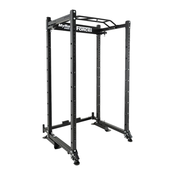
- Page 1 F-MR-BASE-SPACESAVER-V2...
-
Page 2: Important Assembly Information
IMPORTANT ASSEMBLY INFORMATION NOTE: It is strongly recommended that this equipment is assembled by two or more people to avoid possible injury. FASTENING NUTS AND BOLTS Only tighten all nuts and bolts after all components have been fully assembled. Do not over tighten any component with pivoting function. -
Page 3: Assembly Manual
It is the owner’s responsibility to ensure that all users of this unit have read the owner’s manual and are familiar with the safety precautions. We recommended you keep these instructions. FORCE USA TRAINING APP The Force USA Training App Offers Programs, Tutorials, Progress Tracking and More. DOWNLOAD NOW Not compatible with all Force USA equipment. - Page 4 TABLE OF CONTENTS...
-
Page 5: Parts List
PARTS LIST NOTE: SOME PARTS MAY COME PRE ASSEMBLED, IN WHICH CASE CONTINUE ONTO THE NEXT REQUIRED STEP OF ASSEMBLY... - Page 6 PARTS LIST MEASURING FOR BOTH LENGTH...
- Page 7 PICTURE PICTURE DESCRIPTION Back Left Stand Tube Assembly Back Link Short Tube Weldment Left Back Link Short Tube Weldment Right Back Right Stand Tube Assembly Back Link Tube Welding Back Upper Link Tube Assembly Upper Link Tube Left Assembly Down Link Tube Left Assembly Down Link Tube Right Assembly...
- Page 8 PICTURE PICTURE DESCRIPTION Upper Link Tube Right Assembly φ12×160-M100 uter Wire Shaft Decorative Aluminium Cover Front Stand Pillar Assembly φ12.8×220- M100 uter Wire Shaft Chin Up Bracket Assembly Ground Feet Assembly φ22×φ18×φ12×1 3 Interval Cover Down Fixing Plate...
- Page 9 PICTURE DESCRIPTION PICTURE φ12x75-M8 Inner Wire Shaft Ground Foot Spring...
-
Page 10: Assembly Step
ASSEMBLY STEP 1... - Page 11 1. Connect Back Link Short Tube Weldment Le�-2 and Back Le� Stand Tube Assembly-1 use Hexagon Head Bolt-7, Flat Washer-6 and Lock Nut-8. 2. Connect Back Link Short Tube Weldment Right-3 and Back Right Stand Tube Assembly-4 use Hexagon Head Bolt-7, Flat Washer-6 and Lock Nut-8. 3.
- Page 12 (4)Back Right Stand Tube Assembly 1 pc/ Machine...
- Page 13 (1)Back Left Stand Tube Assembly 1 pc/ Machine...
- Page 14 ASSEMBLY STEP 2...
- Page 15 Fix Back Upper Link Tube Assembly-10 on main frame use Hexagon Head Bolt-11, Flat Washer-6 and Lock Nut-8.
- Page 16 (10)Back Upper Link Tube Assembly 1 pc/ Machine...
- Page 17 ASSEMBLY STEP 3...
- Page 18 1. Fix Upper Link Tube Le� Assembly-12 on main frame, use Outer Wire Sha�-16, Flat Washer-18 and Lock Nut-19. 2. Fix Upper Link Tube Right Assembly-15 on main frame, use Outer Wire Sha�-16, Flat Washer-18 and Lock Nut-19. 3. Fix Down Link Tube Le� Assembly-13 on main frame, use Decora�ve Aluminium Cover-17, Spring Gasket-20 and Inner Hexagon Flat Round Head Screw-21.
- Page 19 (15)Upper Link Tube Right Assembly 1 pc/ Machine...
- Page 20 (12)Upper Link Tube Left Assembly 1 pc/ Machine...
- Page 21 (14)Down Link Tube Right Assembly 1 pc/ Machine...
- Page 22 (13)Down Link Tube Left Assembly 1 pc/ Machine...
- Page 23 ASSEMBLY STEP 4...
- Page 24 1. Fix Chin Up Bracket Assembly-24 on main frame, right side fixed by Outer Wire Sha�-23, Flat Washer-18 and Lock Nut-19. 2. Fix Front Stand Pillar Assembly-22 on main frame, top side fixed by Hexagon Head Bolt-11,Flat Washer-6 and Lock Nut-8, down side fixed by Hexagon Head Bolt-25, Spring Gasket-26 and Flat Washer-6.
- Page 25 (22)Front Stand Tube Assembly 2 pcs/ Machine...
- Page 26 (24) Chin Up Bracket Assembly 1 pc/ Machine...
- Page 27 ASSEMBLY STEP 5 32 28 32 33...
- Page 28 1. Connect Ground Feet Assembly-27 with Down Fixing Plate-29 use Inner Wire Sha�-30, Interval Cover-28, Flat Washer-32, Spring Washer-33 and Hexagon Head Bolt-34. A�en�on: the middle down side of Inner Wire Sha�-30 should cross Ground Foot Spring-31. F 2. Fix the connected Ground Feet Assembly-27 and Down Fixing Plate-29 on the main frame, use Hexagon Head Bolt-7, Flat Washer-6 and Lock Nut-8.
- Page 29 Ground Foot Assembly...
-
Page 30: Warranty
It comes from the urge to push boundaries and break through barriers. We know this because we’ve been there from selling the first piece of Force USA gear in 2007 to providing commercial and home gym equipment all over the globe. We are for helping you become your strongest self.
Need help?
Do you have a question about the F-MR-BASE-SPACESAVER-V2 and is the answer not in the manual?
Questions and answers