
Subscribe to Our Youtube Channel
Related Manuals for Siemens SITRANS F FX330


Summary of Contents for Siemens SITRANS F FX330
- Page 1 Operating Instructions SITRANS F Vortex flowmeters SITRANS FX330 Edition 05/2019 www.siemens.com/flow...
- Page 2 IMPRINT :::::::::::::::::::::::::::::::::: All rights reserved. It is prohibited to reproduce this documentation, or any part thereof, without the prior written authorisation of Siemens. Subject to change without notice. Copyright 2019 by Siemens www.siemens.com/flow 05/2019 - A5E36751269-AE...
-
Page 3: Table Of Contents
3.8.2 Installing devices in sandwich design .................. 35 3.8.3 Installing devices in flange design ..................36 3.8.4 Mounting the field housing, remote version ................ 37 3.9 Heat insulation........................ 38 3.10 Turning the connection housing................... 39 3.11 Turning the display ....................... 40 05/2019 - A5E36751269-AE www.siemens.com/flow... - Page 4 6.8 Setting examples ......................87 6.8.1 Settings for free air delivery measurement - FAD............... 87 6.8.2 Gross heat measurement ..................... 88 6.8.3 Net heat measurement......................89 6.9 Status messages and diagnostic information..............90 6.10 A12 plausibility checks ....................96 www.siemens.com/flow 05/2019 - A5E36751269-AE...
- Page 5 8 Technical data 8.1 Functional principle...................... 101 8.2 Technical data....................... 102 8.3 Dimensions and weights ....................108 8.3.1 Flange versions........................108 8.3.2 Sandwich versions ......................115 8.3.3 Remote version ........................117 8.4 Flow tables ........................118 9 Notes 05/2019 - A5E36751269-AE www.siemens.com/flow...
-
Page 6: Safety Instructions
Edition 05/2019 09/2019 ER 2.0.5_ 1; 2-F Edition 05/2019 09/2019 ER 2.0.5_ (01-01) 1; 2-P Edition 05/2019 Table 1-2: Changes and effect on compatibility 1 Incompatible change: hardware change 2 Incompatible change: new communication interface functions www.siemens.com/flow 05/2019 - A5E36751269-AE... -
Page 7: Intended Use
Primarily, volumetric flow and temperature are measured, with pressure measurement as an option. From these parameters the measuring device calculates the mass flow or standard volumetric flow using pre-programmed density data and then exports the measured values via various communication interfaces. 05/2019 - A5E36751269-AE www.siemens.com/flow... - Page 8 = 0.7 m/s / 2.3 ft/s in SIL mode for liquid application. INFORMATION! DN15C and DN25C have a robust flow sensor (signal pick-up) for harsh measuring conditions and higher maximum velocity compared to the standard version. www.siemens.com/flow 05/2019 - A5E36751269-AE...
-
Page 9: Certifications
DANGER! For devices used in hazardous areas, additional safety notes apply; please refer to the Ex documentation. CAUTION! For devices used in SIL applications, additional safety notes apply. For detailed information refer to the "Safety Manual". 05/2019 - A5E36751269-AE www.siemens.com/flow... -
Page 10: Pressure Equipment Directive
• The draining of the device will be performed in the same way as the connected pipeline. • Protect devices from vibration and high-frequency oscillation. • Implement appropriate measures to counteract external fire hazards www.siemens.com/flow 05/2019 - A5E36751269-AE... -
Page 11: Safety Instructions From The Manufacturer
The manufacturer reserves the right to alter the content of its documents, including this disclaimer in any way, at any time, for any reason, without prior notification, and will not be liable in any way for possible consequences of such changes. 05/2019 - A5E36751269-AE www.siemens.com/flow... -
Page 12: Product Liability And Warranty
This document is provided to help you establish operating conditions, which will permit safe and efficient use of this device. Special considerations and precautions are also described in the document, which appear in the form of icons as shown below. www.siemens.com/flow 05/2019 - A5E36751269-AE... -
Page 13: Warnings And Symbols Used
In general, devices from the manufacturer may only be installed, commissioned, operated and maintained by properly trained and authorized personnel. This document is provided to help you establish operating conditions, which will permit safe and efficient use of this device. 05/2019 - A5E36751269-AE www.siemens.com/flow... -
Page 14: Device Description
• Dual version with two flow sensors and two signal converters The following designs are available as options: • With pressure sensor - with or without shut-off valve • Flange version, flow sensor with single reduction F1R • Flange version, flow sensor with double reduction F2R www.siemens.com/flow 05/2019 - A5E36751269-AE... -
Page 15: Flange Versions
The sandwich version features 2 centering rings to aid with installation. Figure 2-3: Sandwich versions with display 1 Version with temperature sensor 2 Version with temperature sensor and optional pressure sensor 3 Version with temperature sensor, optional pressure sensor and shut-off valve 05/2019 - A5E36751269-AE www.siemens.com/flow... -
Page 16: Dual Version And Twofold Reliability
In such pipelines, two different products are moved through one after the other. One signal converter can be programmed for one product, and the other signal converter for the other product. Figure 2-4: Dual version and twofold reliability www.siemens.com/flow 05/2019 - A5E36751269-AE... -
Page 17: Remote Version
4 Wall mount bracket connection box With the remote version, the flow sensor and signal converter are installed separately in different places. The 6-pin, shielded connection cable is available with a length up to 50 m / 164 ft. 05/2019 - A5E36751269-AE www.siemens.com/flow... -
Page 18: Devices With Integrated Nominal Diameter Reduction
DN25 StV 1 DN40 StV 1 DN50 StV 1 DN80 StV 1 DN100 StV 1 DN150 StV 1 DN200 StV 1 DN250 StV 1 DN300 StV 1 Table 2-1: Integrated nominal diameter reduction 1 Standard version www.siemens.com/flow 05/2019 - A5E36751269-AE... -
Page 19: Device Description
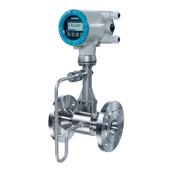
DEVICE DESCRIPTION SITRANS FX330 2.2.6 Device description Figure 2-6: Device description 1 Signal converter 2 Cable feed through 3 Pressure sensor, optional 4 Shut-off valve, optional 5 Flow sensor 6 Centering ring 05/2019 - A5E36751269-AE www.siemens.com/flow... -
Page 20: Free Air Delivery Measurement - Fad (Optional)
Extras" if not unlocked by order. Please contact the manufacturer to obtain the four digit code required to enable this feature. For programming example refer to Settings for free air delivery measurement - FAD on page www.siemens.com/flow 05/2019 - A5E36751269-AE... -
Page 21: Gross Heat Measurement (Optional)
Heat quantity calculation is an optional feature, which can be unlocked subsequently in menu "C6.3 Extras" if not unlocked by order. Please contact the manufacturer to obtain the four digit code required to enable this feature. For programming example refer to Gross heat measurement on page 88 05/2019 - A5E36751269-AE www.siemens.com/flow... -
Page 22: Net Heat Measurement (Optional)
Heat quantity calculation is an optional feature, which can be unlocked subsequently in menu • "C6.3 Extras" if not unlocked by order. Please contact the manufacturer to obtain the four digit code required to enable this feature. For programming examples refer to Net heat measurement on page 89 www.siemens.com/flow 05/2019 - A5E36751269-AE... -
Page 23: Dual Seal
Even though there is no reason to expect the seal to fail, regular visual checks should still be carried out to detect any possible leak as early as possible. In the event of a leak, contact the manufacturer's service department to service or replace the device. 05/2019 - A5E36751269-AE www.siemens.com/flow... -
Page 24: Nameplate
4 Manufacturing year, connection data, material and K factor 5 PED data 6 Fluid data 7 Ex data according to notified body (only available if this option was ordered) 8 Electrical connection data 9 Safety instructions, disposal and data matrix www.siemens.com/flow 05/2019 - A5E36751269-AE... - Page 25 7 Ex data according to notified body (only available if this option was ordered) 8 Electrical connection data 9 Safety instructions, disposal and data matrix Figure 2-11: Example of additional nameplate 1 Serial number 2 Order number 3 Production order number 4 Product designation 5 Article code 05/2019 - A5E36751269-AE www.siemens.com/flow...
-
Page 26: Installation
Non-secured devices can pose risk of injury. The centre of mass of the device is often higher than the point at which the lifting straps are attached. Prevent the measuring device from sliding or rotating accidentally. www.siemens.com/flow 05/2019 - A5E36751269-AE... -
Page 27: Installation Conditions
If there is a risk of water hammers in steam networks, appropriate condensate separators must be installed. Suitable measures must be taken to avoid water cavitation if it is a possible risk. INFORMATION! The pressure sensor must be protected against ambient effects of frost. 05/2019 - A5E36751269-AE www.siemens.com/flow... -
Page 28: Installation When Measuring Liquids
1 If the device is installed in a downpipe, a standpipe must be installed immediately after it 2 Installing the device in an inclined standpipe 3 Installing the device in a vertical standpipe 4 Installing the device in the lower pipe bend www.siemens.com/flow 05/2019 - A5E36751269-AE... - Page 29 Installing the device in an upper pipe bend 3, there is a risk of gas bubbles forming. • Gas bubbles can lead to pressure surges and inaccurate measurement. 05/2019 - A5E36751269-AE www.siemens.com/flow...
-
Page 30: Installation When Measuring Steam And Gases
Installing the device in a lower pipe bend: there is a risk of condensate forming. Condensate can lead to cavitation and inaccurate measurement. Under certain circumstances the device can be destroyed and the measured medium can leak. www.siemens.com/flow 05/2019 - A5E36751269-AE... -
Page 31: Pipelines With Control Valve
2 Underneath a horizontal pipe (not permitted with lines at risk of condensate forming) 3 On a vertical pipe 4 Horizontal pipeline with signal converter-orientation 90° to the side INFORMATION! Depending on the installation position, you may have to rotate the display and/or the connection housing. 05/2019 - A5E36751269-AE www.siemens.com/flow... -
Page 32: Minimum Inlet Sections
7 Outlet section > 5 DN INFORMATION! The nominal diameter of the flange is significant for the determination of the minimum inlet and outlet sections for the nominal diameter reduced versions of vortex flowmeter versions F1R and F2R. www.siemens.com/flow 05/2019 - A5E36751269-AE... -
Page 33: Minimum Outlet Sections
Figure 3-10: Flow straightener 1 Straight inlet section upstream of straightener ≥ 2 DN 2 Flow straightener 3 Straight pipe run between flow straightener and device ≥ 8 DN 4 Minimum straight outlet section ≥ 5 DN 05/2019 - A5E36751269-AE www.siemens.com/flow... -
Page 34: Installation
The internal diameter of the pipelines, the flow sensor and the gaskets must match. The gaskets may not protrude into the flow. Figure 3-12: Inner diameter 1 Inner diameter of connection pipe 2 Inner diameter of flange and gasket 3 Inner diameter of flow sensor www.siemens.com/flow 05/2019 - A5E36751269-AE... -
Page 35: Installing Devices In Sandwich Design
• Turn the centring ring 2 in a counter-clockwise direction and align the device. • Check that the gaskets 5 are concentric; they must not protrude into the pipe cross-section. • Now tighten all nuts bit by bit alternately across the diagonal. 05/2019 - A5E36751269-AE www.siemens.com/flow... -
Page 36: Installing Devices In Flange Design
• Install the gasket, bolts and fastening nuts on the other side of the flange. • Align the measuring device and the gaskets so they are concentric. • Now tighten all nuts bit by bit alternately across the diagonal. www.siemens.com/flow 05/2019 - A5E36751269-AE... -
Page 37: Mounting The Field Housing, Remote Version
U-brackets (Ø8 mm / 0.3") in case of pole installation. In case of mounting directly to the wall, a mounting system with a minimum load force of 0.1 kN (for example FISCHER type UX10) suitable for the background has to be applied. 05/2019 - A5E36751269-AE www.siemens.com/flow... -
Page 38: Heat Insulation
1 Max. height of the insulation up to the marking on the neck of the flow sensor 2 Max. thickness of the insulation up to the bend of the pressure pipe 3 Insulation CAUTION! The heat insulation 3 may only extend as far as the bend of the pressure sensing line 2. www.siemens.com/flow 05/2019 - A5E36751269-AE... -
Page 39: Turning The Connection Housing
1 M4 Allen screw on connection housing • Loosen the M4 Allen screw 1 on the side of the connection housing. • Rotate the connection housing to the desired position (0...<360°). • Tighten the M4 Allen screw 1 again. 05/2019 - A5E36751269-AE www.siemens.com/flow... -
Page 40: Turning The Display
• Press the display onto the spacer pins 4, until it clicks. • Turn the cover with gasket 5 back onto the housing and tighten it by hand. INFORMATION! Before closing the housing cover refer to Maintaining the O-rings on page 98 www.siemens.com/flow 05/2019 - A5E36751269-AE... -
Page 41: Electrical Connections
Any work done on the electrical components of the measuring device may only be carried out by properly trained specialists. INFORMATION! Look at the device nameplate to ensure that the device is delivered according to your order. Check for the correct supply voltage printed on the nameplate. 05/2019 - A5E36751269-AE www.siemens.com/flow... -
Page 42: Connecting The Signal Converter
• Turn the housing cover and gasket back onto the housing and tighten it by hand. INFORMATION! Ensure that the housing gasket is properly fitted, clean and undamaged. Before closing the housing cover refer to Maintaining the O-rings on page 98 www.siemens.com/flow 05/2019 - A5E36751269-AE... -
Page 43: Electrical Connections
Connect current loop 4..20 mA to terminals C1+ and C2-. When connection cables are long, a shielded or twisted cable may be necessary. The cable shield may only be grounded at one place (e.g. on the power supply unit). 05/2019 - A5E36751269-AE www.siemens.com/flow... -
Page 44: Current Input
C2.2 prior to first use. The binary output is electrically separated from the current output and must be supplied with power separately. www.siemens.com/flow 05/2019 - A5E36751269-AE... -
Page 45: Limit Switch Output
• M2/4 and M3 - NAMUR (DC interface in accordance with EN 60947-5-6) • M2/4 and M1 - Transistor output (passive, open collector) Terminal M2/4 Connection NAMUR + (open collector, Common ~ 1 kΩ) Connection transistor output + (open collector, Common < 100 mA) Table 4-1: Terminal connection 05/2019 - A5E36751269-AE www.siemens.com/flow... - Page 46 The upper limit of the signal current must not be exceeded as this may damage the transistor output. For selection of measurement variable and adjustable data of the limit switch refer to chapter "Menu description C - Setup", menu "C2.2.5 Limit Switch" and appropriate submenus. www.siemens.com/flow 05/2019 - A5E36751269-AE...
-
Page 47: Pulse Output / Frequency Output
For selection of measurement variable and adjustable data of the pulse or frequency output refer to chapter "Menu description C - Setup", menu "C2.2.2 Pulse Output" or menu "C2.2.3 Frequency Output" and appropriate submenus. INFORMATION! Make sure the pulse width is in line with the pulse rate. 05/2019 - A5E36751269-AE www.siemens.com/flow... -
Page 48: Status Output
Figure 4-7: Connection terminals of remote version The connection terminals in the connection box of the flow sensor and the wall bracket are identical in construction. Terminals Strand colour blue black grey yellow green gnye Shielding Table 4-5: Connection cable strand colour www.siemens.com/flow 05/2019 - A5E36751269-AE... - Page 49 The maximum cable length is 50 m / 164 ft. The cable can be shortened easily. All wires must be connected afterwards. CAUTION! Please ensure that the shielding 4 has been properly connected to both terminals 3 and 5. 05/2019 - A5E36751269-AE www.siemens.com/flow...
-
Page 50: Grounding Connections
Figure 4-10: Grounding connection for remote version 1 Electrical grounding connection on flow sensor 2 Electrical grounding connection on signal converter housing INFORMATION! In the remote version, the flow sensor as well as the signal converter must be grounded. www.siemens.com/flow 05/2019 - A5E36751269-AE... -
Page 51: Ingress Protection
• Align the measuring device so that the cable feedthrough is never facing up 3. • Close any unused cable feedthroughs using blind plugs 4 suitable for the protection category. • Do not remove the required cable bushing from the cable feedthrough. 05/2019 - A5E36751269-AE www.siemens.com/flow... -
Page 52: Start-Up
5.2 Operation INFORMATION! The measuring device is largely maintenance-free. Observe the application limits in respect of temperature and medium. www.siemens.com/flow 05/2019 - A5E36751269-AE... -
Page 53: Operation
4 1st measured variable in large representation 5 Indicates when a key has been pressed 6 Tag number (only shown if entered previously by the operator) 7 Indicates a possible status message in the status list 05/2019 - A5E36751269-AE www.siemens.com/flow... -
Page 54: Display For Selection Of Submenu And Functions, 3 Lines
(_ _ _ signals in this line the end of the list) 6 Current menu(s), submenu or function 7 Previous menu(s), submenu or function (_ _ _ signals in this line the beginning of the list) www.siemens.com/flow 05/2019 - A5E36751269-AE... -
Page 55: Display When Setting Parameters, 4 Lines
3 Denotes a changed parameter (simple check of changed data when browsing through lists) 4 Next parameter 5 Currently set data from 6 6 Current parameter (for selection press key >; then see previous chapter) 7 Factory setting of parameter 05/2019 - A5E36751269-AE www.siemens.com/flow... -
Page 56: Basic Principles Of Operation
• Press the ^ button to save the settings, or to reject them. • Before returning to measuring mode, you are prompted "Save Configuration?" which you need to accept with "Yes". Switch between "Yes", "Back" and "No" by pressing the ↑ or ↓ keys. www.siemens.com/flow 05/2019 - A5E36751269-AE... -
Page 57: Character Selection In Change Mode
Table 6-3: Example: Changing the default parameter from m /h to l/h 6.2.4 Character selection in change mode Depending on the menu function, the following characters are available: Numbers Lower case letters Upper case letters Special characters ..05/2019 - A5E36751269-AE www.siemens.com/flow... -
Page 58: Units, Figures And Factors
The "User" access level does not have a specific password – if you enter any password not assigned to a level, e.g. "0000" (which is an invalid password), you will fall back to "User" access level. www.siemens.com/flow 05/2019 - A5E36751269-AE... - Page 59 In case the user has changed particular passwords from their default settings and is not able to log in anymore, there is a "Reset Passwords" command available in the C6.2.3 submenu. However to prevent unauthorised use this command itself is protected by a non-changeable unique password available by contacting the manufacturer. 05/2019 - A5E36751269-AE www.siemens.com/flow...
-
Page 60: Overview Of The Most Important Functions And Units
Spanish Swedish Danish Czech Polish Russian Chinese Turkish Slovenian In preparation: In preparation: In preparation: In preparation: Dutch Portuguese Slovak Hungarian Lithuanian Norwegian Finnish Estonian Latvian Moldavian Bulgarian Romanian Albanian Table 6-7: List of menu languages www.siemens.com/flow 05/2019 - A5E36751269-AE... -
Page 61: Gas Options For Gas Measurement
To enter shares > 9.99999 % the point can be shifted rightwards by moving the cursor to the point and then press the upwards button ↑. Change between the digits by pressing the rightwards button →. After reaching the last digit the cursor will jump again to the first digit. 05/2019 - A5E36751269-AE www.siemens.com/flow... -
Page 62: Units
Table 6-10: Units for norm./standard* volume flow * The units Nx/x and Sx/x shall be considered as equivalent. They serve as an indication for a normalised or standardised measuring variable and do not identify the underlying reference system. www.siemens.com/flow 05/2019 - A5E36751269-AE... - Page 63 Customised volume Table 6-12: Totalizer units * The units Nx and Sx shall be considered as equivalent. They serve as an indication for a normalised or standardised measuring variable and do not identify the underlying reference system. 05/2019 - A5E36751269-AE www.siemens.com/flow...
- Page 64 The pressure unit psi (abs) refers to a reference point of 0 bara / 0 psia. All other pressure units are gauge pressure units and refer to a reference pressure of 1.01325 bara / 14.7 psia (acc. to DIN 1343). www.siemens.com/flow 05/2019 - A5E36751269-AE...
-
Page 65: Menu Structure
A9.22 Cst. Density A10 Meter Type A11 Application A11.1 Liquids Assistant A11.2 Saturated Steam A11.3 Superheated Steam A11.4 Heat Measurement A11.5 Gas A11.6 FAD A12 Cluster Cluster 1...12 Checks Table 6-14: Menu overview "A Quick Setup" 05/2019 - A5E36751269-AE www.siemens.com/flow... -
Page 66: Menu Overview "B Test
B2.2 Volume Flow B2.3 Norm. Volume Flow B2.4 Mass Flow B2.5 Gross Power B2.6 Net Power B2.7 FAD B2.8 Volume B2.9 Norm. Volume B2.10 Mass B2.11 Gross Energy B2.12 Net Energy B2.13 Density B2.14 Temperature1 B2.15 Temperature2 www.siemens.com/flow 05/2019 - A5E36751269-AE... -
Page 67: Menu Overview "C Setup
C1.6 Temp. Sensor C1.6.1 Temp. Source1 C1.6.2 Temp. Source2 C1.7 Pressure C1.7.1 Pressure Source Sensor C1.8 Time Constant C1.9 Low Flow Cutoff C1.10 Operating C1.10.1 Oper. Temperature Values C1.10.2 Oper. Pressure C1.10.3 Oper. Density C1.10.4 Min/Max Oper. Dens. 05/2019 - A5E36751269-AE www.siemens.com/flow... - Page 68 C4.1.3 Reset Totalizer? C4.1.4 Set Start Value C4.1.5 Start Totalizer? C4.1.6 Stop Totalizer? C4.1.7 Information C4.2 Energy Totalizer C4.2.1 Measurement C4.2.2 Preset Value C4.2.3 Reset Totalizer? C4.2.4 Set Start Value C4.2.5 Start Totalizer? C4.2.6 Stop Totalizer? C4.2.7 Information www.siemens.com/flow 05/2019 - A5E36751269-AE...
- Page 69 C6.1.8 Electronic Revision C6.1.9 Device Revision C6.1.10 Software Revision C6.1.11 Hardware Revision C6.1.12 Electronic Serial No. C6.1.13 CG Number C6.1.14 Production Date C6.1.15 Calibration Date C6.2 Security C6.2.1 Login C6.2.2 Change Password C6.2.3 Reset Passwords C6.2.4 Unlock SIL 05/2019 - A5E36751269-AE www.siemens.com/flow...
- Page 70 C6.8 Proof Test C6.8.2 Run Proof Test? Table 6-16: Menu overview "C Setup" 1 In all even numbered menus C6.5.2 to .22 Cst. Units (Custom Units) there is a submenu with the prompt for "Text", "Offset" and "Factor". www.siemens.com/flow 05/2019 - A5E36751269-AE...
-
Page 71: Menu Description "A Quick Setup
FAD functionality. A11 Application Assistant For details refer to next tables. A12 plausibility checks A12 Cluster Checks For further information refer to on page 96. Table 6-17: Menu description "A Quick Setup" 05/2019 - A5E36751269-AE www.siemens.com/flow... - Page 72 Configuration of gas applications with optionally internal or external pressure and temperature sources for the density compensation. A11.6 FAD Configuration of FAD (Free Air Delivery) applications for compressors. Table 6-18: A11.1 Application Assistant - general options www.siemens.com/flow 05/2019 - A5E36751269-AE...
- Page 73 One Value / Two Values / Three Values / One Value & Bargraph / Two values & Bargraph .14 2. Meas. Page One Value / Two Values / Three Values / One Value & Bargraph / Two values & Bargraph Table 6-19: A11.1 Application Assistant - Liquids 05/2019 - A5E36751269-AE www.siemens.com/flow...
- Page 74 Enter low flow cutoff point in current volume flow unit. .4 Current Input .4.1 Function Select "On", if applicable. .4.2 Current Input Meas. Select "Temperature External" or "Pressure External". .5.1 Temp. Source1 Internal / External / External HART / Not Available www.siemens.com/flow 05/2019 - A5E36751269-AE...
- Page 75 Internal / External / External HART / Not Available .5.2 Temp. Source2 Internal / External / External HART / Not Available Temperature source 1 and 2 must be different. .6 Operating Values Same options as in A11.1.4. .7 Current Output 05/2019 - A5E36751269-AE www.siemens.com/flow...
- Page 76 Internal / External / External HART / Not Available .5.2 Temp. Source2 Internal / External / External HART / Not Available Temperature source 1 and 2 must be different. .6 Gas Mixture If fluid = "Gas Mixture", enter gas mixture in %. www.siemens.com/flow 05/2019 - A5E36751269-AE...
- Page 77 Internal / External / External HART / Not Available Temperature source 1 and 2 must be different. .6 Gas .6.1 Inlet Temperature Enter temperature on inlet side in selected unit. .6.2 Atm. Pressure Enter current ambient pressure in selected unit. 05/2019 - A5E36751269-AE www.siemens.com/flow...
-
Page 78: Menu Description "B Test
"C6.3 Extras". For this purpose an activation password is necessary. Please contact the manufacturer. When using the standard device all menu entries concerning heat measurement, density calculation and FAD are hidden. www.siemens.com/flow 05/2019 - A5E36751269-AE... - Page 79 (Pressure sensor support only available for meter types "Heat & Dens. by Pres." and "Heat & Dens. & FAD") C1.8 Time Constant Enter: 0...100 s C1.9 Low Flow Cutoff Sets low flow values to "0". Enter value for low flow cutoff in volumetric flow unit. 05/2019 - A5E36751269-AE www.siemens.com/flow...
- Page 80 C2.1.5 Upper Ext. Range Maximum limit of current value. Pre-set value is 20 mA. Enter: 20…20.5 mA Condition for value > 20 mA: Measurement value at 20 mA must not be greater or equal to 100%. www.siemens.com/flow 05/2019 - A5E36751269-AE...
- Page 81 Enter value for 0% range in unit according to measurement variable selection. C2.2.3.7 100% Range Enter value for 100% range in unit according to measurement variable selection. C2.2.4 Status Output Only available, if "Status" is selected in C2.2.1. 05/2019 - A5E36751269-AE www.siemens.com/flow...
- Page 82 Standard setting is 000 for point-to-point operation with current output 4…20 mA. Setting of polling address ≠ 000 causes a constant 4 mA output and enables multi-drop mode. Enter: 000…063 C3.1.2.2 Tag Enter measuring point identifier (1…8 digits). www.siemens.com/flow 05/2019 - A5E36751269-AE...
- Page 83 Entry will be displayed in the header bar on the LC display (depending on letter size, min. 11 digits can be displayed). C3.1.2.4 Manufacturer ID ® HART Manufacturer ID = 00042 (0x2A) [SIEMENS] (read-only) C3.1.2.5 Device Type Device Type = 00058 (0x3A) (read-only) C3.1.2.6 Device ID Individual device ID (read-only) C3.1.2.7 Universal Revision...
- Page 84 Adjust contrast of local display (-10...+10). C5.3 1. Meas. Page Configuration of the first measurement display page. C5.3.1 Function Select: One Value / Two Values / Three Values / One Value & Bargraph / Two Values & Bargraph www.siemens.com/flow 05/2019 - A5E36751269-AE...
- Page 85 Display of meter type as activated in A10 or C6.3.2...C6.3.4 (read-only). C6.1.4 Serial Number Individual device ID (read-only). C6.1.5 Manufacturer ID ® HART Manufacturer ID = 00042 (0x2A) [SIEMENS] (read-only) C6.1.6 Device Name SITRANS FX330 (read-only) C6.1.7 V Number Internal order number (read-only). C6.1.8 Electronic Revision...
- Page 86 Query: Reset to Fact. Def.? Press "→" and confirm reset to factory default with "Yes" or refuse with "No". C6.8 Proof Test For details refer to the "Safety Manual". Table 6-32: Menu description C6.5 - C6.8 www.siemens.com/flow 05/2019 - A5E36751269-AE...
-
Page 87: Setting Examples
C5.3.3 0% Range; C5.3.4 100% Range Enter bargraph range limits (0% / 100%) in selected unit. Table 6-33: Settings for free air delivery measurement - FAD INFORMATION! This is an example setup for basic FAD measurement. Other setup options are feasible. 05/2019 - A5E36751269-AE www.siemens.com/flow... -
Page 88: Gross Heat Measurement
C5.3.1 Function Two Values C5.3.2 Measurement 1. Line Gross Power C5.3.6 Measurement 2. Line Gross Energy Table 6-34: Gross heat measurement INFORMATION! This is an example setup for basic gross heat measurement. Other setup options are feasible. www.siemens.com/flow 05/2019 - A5E36751269-AE... -
Page 89: Net Heat Measurement
C5.3.1 Function Two Values C5.3.2 Measurement 1. Line Net Power C5.3.6 Measurement 2. Line Net Energy Table 6-35: Net heat measurement INFORMATION! This is an example setup for basic net heat measurement. Other setup options are feasible. 05/2019 - A5E36751269-AE www.siemens.com/flow... -
Page 90: Status Messages And Diagnostic Information
No direct influence on the measurements. Table 6-36: Symbols for status messages INFORMATION! Some of the following elimination measures require a hard reset. In case a hard reset is performed please wait for approx. 10 seconds before powering the device again. www.siemens.com/flow 05/2019 - A5E36751269-AE... - Page 91 Piezo Path disrupted Sensor electronics error. Perform a hard reset. If the message recurs, contact the manufacturer. Piezo Shortcut Shortcut on piezo or sensor Perform a hard reset. If the electronics detected. message recurs, contact the manufacturer. 05/2019 - A5E36751269-AE www.siemens.com/flow...
- Page 92 If inconsistent set of the message recurs, contact parameter. the manufacturer. Incons. Converter Calib. Faulty calibration data in the Contact the manufacturer. converter module. Incons. Sensor Calibration Faulty calibration data in the sensor module. www.siemens.com/flow 05/2019 - A5E36751269-AE...
- Page 93 SIL Prooftest Device is in maintenance Perform the test according mode 3 (proof test for SIL). to the instruction in the "Safety Manual". Parameterization Test Device is in maintenance mode 3 (parameterization test). 05/2019 - A5E36751269-AE www.siemens.com/flow...
- Page 94 Sensor Information Faulty Sensor Oscillator The sensor oscillator is Perform a hard reset. If the working out of range. message recurs, contact the manufacturer. Faulty sensor voltage ref. Reference voltage in sensor module out of specification. www.siemens.com/flow 05/2019 - A5E36751269-AE...
- Page 95 Reference voltage in converter module out of specification. Process Heater / Cooler Error During net heat metering Check net heat metering the difference in setup. temperature is reversed. Check temperature input configuration. Table 6-37: Status messages 05/2019 - A5E36751269-AE www.siemens.com/flow...
-
Page 96: A12 Plausibility Checks
HART Catch ® If temperature or pressure data input is provided by HART , the device checks if the "Slot Variable Number" fits in with the "Capture Command". (Temperature / Pressure) Table 6-38: A12 plausibility checks www.siemens.com/flow 05/2019 - A5E36751269-AE... -
Page 97: Service
• Insert new signal converter. • Tighten the two screws 6. • Attach the flow sensor cable 5. • Attach display 1 in desired position, apply even pressure to the entire surface. • Screw on cover by hand. 05/2019 - A5E36751269-AE www.siemens.com/flow... -
Page 98: Maintaining The O-Rings
O-rings with the following properties: Operational temperature range (-30...+130 C / -22...+266 F at permanent lubrication) • ° ° Free from silicone • Good adhesive capability • • Lithium saponified Water resistant • Compatible with material of O-ring • www.siemens.com/flow 05/2019 - A5E36751269-AE... -
Page 99: Spare Parts Availability
For more precise information, please contact your local sales office. 7.5 Return procedure If the original packaging is no longer available, ensure that all shipments are properly packaged to provide sufficient protection during transport. Siemens cannot assume liability for any costs associated with transportation damages. CAUTION! -
Page 100: Disposal
Required forms Required forms Required forms Required forms • Delivery note • Return goods delivery note (http://www.siemens.com/processinstrumentation/ returngoodsnote) with the following information: - Product (item description) - Number of returned devices/replacement parts - Reason for returning the item(s) • Decontamination declaration (http://www.siemens.com/sc/declarationofdecontamination) With this declaration you warrant "that the device/replacement part has been carefully... -
Page 101: Technical Data
Stouhal number S S S S describes the relationship between vortex frequency f f f f , width b b b b of the bluff body and the average flow velocity v v v v : S . v The vortex frequency is recorded at the flow sensor and evaluated at the signal converter. Figure 8-1: Functional principle 05/2019 - A5E36751269-AE www.siemens.com/flow... -
Page 102: Technical Data
Local display Graphic display Interface and display German, English, French, Italian, Spanish, Russian, Chinese, Swedish, Danish, Czech, languages Polish, Turkish, Slovenian; 13 further languages (in preparation) Communication interfaces ® HART , Foundation Fieldbus and Profibus PA www.siemens.com/flow 05/2019 - A5E36751269-AE... - Page 103 Medium pressure Max. 100 bar / 1450 psi (higher pressures on request) Ambient pressure Atmosphere Media properties Media properties Media properties Media properties Density Taken into consideration when sizing. Viscosity < 10 cP Reynold's number > 10000 05/2019 - A5E36751269-AE www.siemens.com/flow...
- Page 104 For detailed information on combination flange/pressure rating, refer to section "Dimensions and weights". Sandwich version Sandwich version Sandwich version Sandwich version DN15...100 - PN100 (higher pressures on request) ASME 1/2...4" - 600 lb (higher pressures on request) DN15...100 - 10…20 K (higher pressures on request) www.siemens.com/flow 05/2019 - A5E36751269-AE...
- Page 105 Proximity sensor according to DIN EN 60947-5-6 (NAMUR sensor) or pulse output signal according to VDI/VDE 2188 (category 2) Temperature coefficient 50 ppm/K Residual current < 0.2 mA at 32 V (R = 180 kΩ) Pulse width 0.5...2000 ms 05/2019 - A5E36751269-AE www.siemens.com/flow...
- Page 106 5 x analog input (AI), 2 x totaliser, 1 x analog output (AO) Output data Volume flow, norm. volume flow, mass flow, gross/net power, FAD, density, temperature 1, temperature 2, pressure, vortex frequency, velocity, specific enthalpy, specific heat capacity, Reynolds number, diagnostic data www.siemens.com/flow 05/2019 - A5E36751269-AE...
- Page 107 Other standards and approvals Other standards and approvals Other standards and approvals QPS (USA & Canada) QPS Ordinary Locations NAMUR NE 06, NE 21, NE 23, NE 32, NE 43, NE 53, NE 107 Further approvals on request. 05/2019 - A5E36751269-AE www.siemens.com/flow...
-
Page 108: Dimensions And Weights
169.3 169.5 169.5 80.9 380.3 368.3 362.3 169.3 169.5 169.5 396.8 380.3 368.3 171.5 169.3 169.5 396.8 380.3 368.3 171.5 169.3 169.5 106.3 396.8 380.3 368.3 171.5 169.3 169.5 104.3 396.8 380.3 368.3 171.5 169.3 169.5 www.siemens.com/flow 05/2019 - A5E36751269-AE... - Page 109 492.8 468.8 442.1 229.5 202.8 307.9 492.8 492.8 442.1 229.5 202.8 307.9 492.8 492.8 442.1 229.5 202.8 Table 8-1: Dimensions of flange version EN 1092-1 [mm] 1 F1R - single reduction 2 F2R - double reduction 05/2019 - A5E36751269-AE www.siemens.com/flow...
- Page 110 131.4 143.2 142.6 Weight specifications for version with two signal converters + 3.2 kg / 7.05 lb Table 8-2: Weight of flange version EN 1092-1 [kg] 1 F1R - single reduction 2 F2R - double reduction www.siemens.com/flow 05/2019 - A5E36751269-AE...
- Page 111 169.5 97.0 396.8 380.3 368.3 171.5 169.3 169.5 154.1 416.3 396.8 380.3 191.5 171.5 169.3 154.1 416.3 396.8 380.3 191.5 171.5 169.3 146.0 416.3 396.8 380.3 191.5 171.5 169.3 202.7 442.1 416.3 396.8 202.8 191.5 171.5 05/2019 - A5E36751269-AE www.siemens.com/flow...
- Page 112 71.6 78.1 77.5 75.0 74.4 75.2 74.6 73.9 73.3 107.0 106.4 112.4 111.8 113.5 112.9 107.0 106.4 109.8 109.2 120.4 119.8 152.0 151.4 165.4 155.8 171.7 171.1 Table 8-4: Weight of flange version ASME B16.5 [kg] www.siemens.com/flow 05/2019 - A5E36751269-AE...
- Page 113 6.67 15.6 15.0 14.5 6.76 6.67 6.67 15.6 15.0 14.5 6.76 6.67 6.67 16.4 15.6 15.0 7.54 6.76 6.67 16.4 15.6 15.0 7.54 6.76 6.67 16.4 15.6 15.0 7.54 6.76 6.67 17.4 16.4 15.6 7.54 6.76 05/2019 - A5E36751269-AE www.siemens.com/flow...
- Page 114 157.9 172.2 171.0 165.4 164.1 165.9 164.5 163.0 161.7 236.0 234.7 247.9 246.6 250.3 249.0 236.0 234.7 242.2 240.8 265.5 264.2 335.2 333.9 364.8 343.6 378.7 377.4 Table 8-6: Weight of flange version ASME B16.5 [lb] www.siemens.com/flow 05/2019 - A5E36751269-AE...
-
Page 115: Sandwich Versions
Nominal size Pressure Dimensions [mm] Weight [kg] rating with without Pressure sensor 358.8 169.3 358.3 169.3 362.3 169.5 368.3 169.5 380.3 169.3 396.8 171.5 10.1 Table 8-7: Dimensions and weight of Sandwich version [mm and kg] 05/2019 - A5E36751269-AE www.siemens.com/flow... - Page 116 14.98 6.67 19.4 18.08 3.82 6.22 2.56 15.63 6.75 22.27 20.94 3.82 6.22 2.56 15.63 6.75 22.27 20.94 3.82 6.22 2.56 15.63 6.75 22.27 20.94 Table 8-8: Dimensions and weight of Sandwich version [inch and lb] www.siemens.com/flow 05/2019 - A5E36751269-AE...
-
Page 117: Remote Version
2 F2R - double reduction [mm] 138.5 108.0 275.6 191.2 105.0 97.0 72.0 108.0 72.0 97.0 226.0 ["] 5.46 4.25 10.9 7.53 4.14 3.82 2.84 4.25 0.35 2.84 3.82 8.90 Table 8-11: Dimension b...n b...n [mm and inch] b...n b...n 05/2019 - A5E36751269-AE www.siemens.com/flow... -
Page 118: Flow Tables
14478 286870 3824929 1577 21028 416638 5555167 Values based on air at +20°C / +68°F and 1.013 bara / 14.7 psia and density 1.204 kg/m / 0.0751 lb/ft Table 8-12: Measuring ranges for water and air www.siemens.com/flow 05/2019 - A5E36751269-AE... - Page 119 35334 1288 37737 1808 52054 2053 59574 2273 66371 2419 70884 2890 83215 3282 95237 3634 106102 3867 113318 4197 120858 4767 138318 5279 154099 5617 164578 Table 8-14: Measuring range for saturated steam: 10.5...20 barg 05/2019 - A5E36751269-AE www.siemens.com/flow...
- Page 120 78419 2799 82006 4011 115455 4553 132068 5048 147302 5258 154041 6412 184569 7279 211127 8069 235481 8406 246254 9313 268060 10571 306632 11720 342002 12209 357649 Table 8-16: Measuring range for saturated steam: 150...300 psig www.siemens.com/flow 05/2019 - A5E36751269-AE...
-
Page 121: Notes
NOTES SITRANS FX330 05/2019 - A5E36751269-AE www.siemens.com/flow... - Page 122 NOTES SITRANS FX330 www.siemens.com/flow 05/2019 - A5E36751269-AE...
- Page 123 NOTES SITRANS FX330 05/2019 - A5E36751269-AE www.siemens.com/flow...
- Page 124 For more information www.siemens.com/flow www.siemens.com/processautomation Siemens AG Process Industries and Drives Process Automation 76181 Karlsruhe Germany Product Information...
Need help?
Do you have a question about the SITRANS F FX330 and is the answer not in the manual?
Questions and answers