Sign In
Upload
Download
Table of Contents
Contents
Add to my manuals
Delete from my manuals
Share
URL of this page:
HTML Link:
Bookmark this page
Add
Manual will be automatically added to "My Manuals"
Print this page
×
Bookmark added
×
Added to my manuals
Manuals
Brands
IFM Manuals
Security Sensors
PI1689
Operating instructions manual
IFM PI1689 Operating Instructions Manual
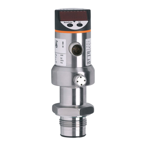
Electronic pressure sensor
Hide thumbs
1
Table Of Contents
2
3
4
5
6
7
8
9
10
11
12
13
14
15
16
17
18
19
20
21
page
of
21
Go
/
21
Contents
Table of Contents
Bookmarks
Table of Contents
Table of Contents
Preliminary Note
1�1 Symbols Used
Safety Instructions
Functions and Features
3�1 Applications
Function
4�1 Processing of the Measured Signals
4�2 Pressure Monitoring/ Analogue Function
Installation
Electrical Connection
Operating and Display Elements
Menu
8�1 Menu Structure
8�2 Menu Explanation
Parameter Setting
9�1 Parameter Setting General
9�2 Configuring the Display (Optional)
9�3 Setting the Output Signal
9�3�1 Setting the Output Function
9�3�2 Scaling the Analogue Value
9�4 User Settings (Optional)
9�4�1 Zero-Point Calibration
9�4�2 Setting the Damping for the Analogue Signal
9�5 Service Functions
9�5�1 Reading the Min�/Max� Values for the System Pressure
9�5�2 Reset All Parameters to the Factory Setting
Operation
10�1 Read the Set Parameter Values
10�2 Fault Indication
10�3 Cleaning of the Filter Cover
Scale Drawing
Advertisement
Quick Links
Download this manual
Operating instructions
Electronic pressure sensor
UK
PI16xx
Table of
Contents
Previous
Page
Next
Page
1
2
3
4
5
Advertisement
Table of Contents
Need help?
Do you have a question about the PI1689 and is the answer not in the manual?
Ask a question
Questions and answers
Related Manuals for IFM PI1689
Accessories IFM PI16 Series Operating Instructions Manual
Electronic pressure sensor (35 pages)
Security Sensors IFM PI299 Series Operating Instructions Manual
Electronic pressure sensor (21 pages)
Security Sensors IFM PI1694 Operating Instructions Manual
Electronic pressure sensor (21 pages)
Security Sensors IFM PI1695 Operating Instructions Manual
Electronic pressure sensor (21 pages)
Security Sensors IFM PI1697 Operating Instructions Manual
Electronic pressure sensor (21 pages)
Security Sensors IFM PI1698 Operating Instructions Manual
Electronic pressure sensor (21 pages)
Security Sensors IFM PI7993 Operating Instructions Manual
Electronic pressure sensor (19 pages)
Security Sensors IFM PN2090 Operating Instructions Manual
Electronic pressure sensor (29 pages)
Security Sensors IFM PN2091 Operating Instructions Manual
Electronic pressure sensor (29 pages)
Security Sensors IFM PN701 Series Operating Instructions Manual
Electronic pressure sensor (29 pages)
Security Sensors IFM PN7032 Operating Instructions Manual
Electronic pressure sensor (29 pages)
Security Sensors IFM PN7034 Operating Instructions Manual
Electronic pressure sensor (29 pages)
Security Sensors IFM PN7191 Operating Instructions Manual
Electronic pressure sensor (27 pages)
Security Sensors IFM PQS Series Operating Instructions Manual
Electronic pressure sensor (57 pages)
Security Sensors IFM PQC Series Operating Instructions Manual
Electronic pressure sensor (58 pages)
Security Sensors IFM PM20 Operating Instructions Manual
Electronic pressure sensor (33 pages)
This manual is also suitable for:
Pi16 series
Pi1693
Pi1694
Pi1695
Pi1696
Pi1697
...
Show all
Pi1698
Pi1699
Table of Contents
Print
Rename the bookmark
Delete bookmark?
Delete from my manuals?
Login
Sign In
OR
Sign in with Facebook
Sign in with Google
Upload manual
Upload from disk
Upload from URL


Need help?
Do you have a question about the PI1689 and is the answer not in the manual?
Questions and answers