Table of Contents
Advertisement
Quick Links
Advertisement
Table of Contents

Subscribe to Our Youtube Channel
Related Manuals for IFM R1D Series


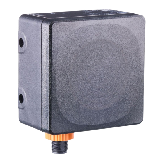
Summary of Contents for IFM R1D Series
- Page 1 Operating instructions IO-Link radar position sensor R1Dx...
-
Page 2: Table Of Contents
R1Dx IO-Link radar position sensor Contents Preliminary note ............. Symbols used . -
Page 3: Preliminary Note
IO-Link radar position sensor R1Dx 1 Preliminary note You will find instructions, technical data, approvals and further information using the QR code on the unit / packaging or at documentation.ifm.com. 1.1 Symbols used Requirement Instructions Reaction, result [...] Designation of keys, buttons or indications... - Page 4 Please note that the firmware for the ifm products is in some cases provided free of charge. The price of the ifm products has then to be paid for the respective device itself (hardware) and not for the firmware. For the latest information on the license agreement for your product please visit www.ifm.com...
-
Page 5: Safety Instructions
IO-Link radar position sensor R1Dx 2 Safety instructions • The unit described is a subcomponent for integration into a system. – The system architect is responsible for the safety of the system. – The system architect undertakes to perform a risk assessment and to create documentation in accordance with legal and normative requirements to be provided to the operator and user of the system. -
Page 6: Cyber Security
R1Dx IO-Link radar position sensor 2.2 Cyber security ATTENTION Unprotected network environment. The device does not include IT security measures according to IEC 62443. w Unauthorised read or write access to data is possible. w Unauthorised manipulation of the device function is possible. u Check and restrict access options to the device. -
Page 7: Intended Use
IO-Link radar position sensor R1Dx 3 Intended use 3.1 Application area Based on FMCW radar, the device monitors an area without contact and detects the distance and speed of stationary and moving objects. Thresholds, switching limits and outputs can be defined. The device is suitable for both mobile (sensor moves) and stationary (sensor is fixed) applications. The dimension of the detection range of the device depends on the target object to be detected. -
Page 8: Restrictions Of The Application Area
R1Dx IO-Link radar position sensor • If required, take appropriate EMC screening measures. The device must be installed in such a way that it cannot be touched by unauthorised persons. 3.2 Restrictions of the application area The device emits high-frequency electromagnetic waves that are reflected by objects and received and evaluated by the device. -
Page 9: Getting Started
2. Connect the device to an IO-Link master and establish a connection between them. 3. Use the Vision Assistant or ifm moneo to make the required settings on the device. The software is required to configure the device. The software can be downloaded at... -
Page 10: Function
5.2 Operating modes The device can only be configured via IO-Link. The software can be downloaded at www.ifm.com. Up to three different operating modes can be set. These differ in the maximum distance, distance resolution, maximum velocity, velocity resolution and switching frequency. -
Page 11: Overview
IO-Link is a communication system for connecting intelligent sensors and actuators to automation systems. IO-Link is standardised in the IEC 61131-9 standard. General information on IO-Link at io-link.ifm Input Output Device Description (IODD) with all parameters, process data and detailed descriptions of the device at... - Page 12 R1Dx IO-Link radar position sensor IO-Link offers the following advantages: • Interference-free transmission of all data and process values • Parameter setting in the running process or presetting outside the application • Parameters for identifying the connected devices in the system •...
-
Page 13: Mounting
Do not paint the device. u Provide strain relief for suitable M12 socket. More information on radar sensor accessories can be found at www.ifm.com. Device performance can be affected if positioned in the immediate vicinity of powerful HF emission sources such as welding transformers. -
Page 14: Mechanical Design
R1Dx IO-Link radar position sensor 6.2 Mechanical design Connection (can be rotated by 270°) Sensing face 6.3 Mounting with clamp u Insert the M5 screws through the through holes of the device and guide them into the threaded M5 holes of the bracket. Tightening torque max. 3.0 Nm. u Fix the clamp to the bracket (E23011). -
Page 15: Mounting With Mounting Bracket
IO-Link radar position sensor R1Dx Fig. 3: Completed installation 6.4 Mounting with mounting bracket By means of the mounting bracket (E23009) the mounting angle of the sensor can be adjusted. A maximum angle of 45° can be set. Fig. 4: Example By means of the mounting bracket (E23010) the mounting angle of the sensor can be adjusted. A maximum angle of 20°... - Page 16 R1Dx IO-Link radar position sensor Fig. 5: Example...
-
Page 17: Electrical Connection
IO-Link radar position sensor R1Dx 7 Electrical connection The unit must be connected by a qualified electrician. Observe the national and international regulations for the installation of electrical equipment. Voltage supply according to SELV, PELV. u Disconnect power. u Connect the unit as follows: OUT2 OUT1/IO-Link Fig. 6: Wiring diagram (colours to DIN EN 60947-5-2) -
Page 18: Pnp/Npn Selection
IO-Link radar position sensor Recommendation: Use pre-configured connection cables / sockets, see accessories at www.ifm.com. The device can be damaged by insufficiently tightened M12 connectors. The IP rating indicated in the data sheet is only guaranteed if the M12 connectors are firmly screwed. -
Page 19: Installation
IO-Link radar position sensor R1Dx 8 Installation To be able to make full use of the device’s functions, the ifm Vision Assistant software is required for parameter setting. u Go to the download section at this link and download the ifm Vision Assistant software onto your computer. -
Page 20: Operating And Display Elements
Status LED flashing red Error (correctable by the operator) Trou- (1 Hz) bleshooting (Ò / 26) Status LED is red Serious error u Contact ifm support. Contact at www.ifm.com Status LED is green, [Find me] function OUT1 and OUT2 (8 Hz) flashing... -
Page 21: Set-Up
After power on, the device is put into operation. After approx. 3 s the device is ready for operation. On delivery, the parameters are set to the factory setting. The device is configured via the ifm Vision Assistant or a suitable IO-Link software. -
Page 22: Parameter Setting
The device parameters can be set in two ways: • IO-Link software, e.g. ifm moneo configure SA • ifm Vision Assistant software (→ see software manual at www.ifm.com) The coordinate system The coordinate system is defined according to the right-hand rule. “Roll”... -
Page 23: R1D100 And R1D200
IO-Link radar position sensor R1Dx 11.1 R1D100 and R1D200 The device has an angle of aperture of ± 20° horizontal and ± 15° vertical (R1D100/R1D102) or ± 10° vertical (R1D200). The FOV of the sensor is fixed and cannot be changed. The radar sensor can detect several targets at the same time, but the process values always refer to one specific target. -
Page 24: Selection Rules
The Vision Assistant displays the field of view and the range profile of the device. You can find the Ò (software manual). instructions for configuring the Vision Assistant at www.ifm.com 11.2 Selection rules You can choose between the following selection rules:... - Page 25 IO-Link radar position sensor R1Dx Selection rule Description [Longest distance] The target that is furthest away from the sensor is selected.
-
Page 26: Troubleshooting
Adjust supply voltage Supply voltage outside the specification (Ò technical data sheet) If the device behaves unexpectedly or incorrectly: u Download and install the latest firmware and ifm Vision Assistant versions (Ò Installation / 19). Download at documentation.ifm.com. u Disconnect the device from the voltage supply (restart) u Restore factory settings, i.e. -
Page 27: Maintenance, Repair And Disposal
IO-Link radar position sensor R1Dx 13 Maintenance, repair and disposal If used correctly, the unit is maintenance-free. u Keep the sensing face and any clear spaces free from deposits and foreign bodies. u It is not possible to repair the unit. Only the manufacturer is allowed to repair the unit. -
Page 28: Approvals / Standards
IO-Link radar position sensor 14 Approvals / standards For approvals and standards, the following information is available: • Test standards and regulations: documentation.ifm.com • EU declaration of conformity and approvals: documentation.ifm.com • Notes relevant for approval: Package insert of the device and documentation.ifm.com... -
Page 29: Factory Setting
IO-Link radar position sensor R1Dx 15 Factory setting The factory settings of the parameters are available at documentation.ifm.com (PDF – IO-Link interface description). -
Page 30: Glossary
R1Dx IO-Link radar position sensor Glossary RCS stands for Radar Cross Section (radar signature) and is a measure of how well a target is detectable by radar, i.e. how much of the emitted energy is reflected from a target. The higher the RCS value, the better the reflectivity and thus the visibility of the target. - Page 31 ð Funkzulassung Radio approval Agrément radio R1D2 R2D2 80308256 / 00 ifm electronic gmbh • Friedrichstraße 1 • 45128 Essen • Germany 11426989 / 00 03 / 2023...
- Page 32 R1D200/R2D200/R2D201/R2D210 Vor Inbetriebnahme die Bedienungsanleitung lesen und während der Einsatzdauer aufbewahren. • Hiermit erklärt die ifm electronic GmbH, dass die oben genannten Geräte der Richtlinie 2014/53/EU entsprechen. • Der vollständige Text der EU-Konformitätserklärung, Technische Daten, Anleitungen, Zulassungen, Kontakte und weitere Informationen unter documentation.ifm.com.
- Page 33 Lire la notice d‘utilisation avant l‘utilisation et conserver-la pendant toute la durée d‘utilisation. • ifm electronic gmbh déclare par la présente que l‘équipement correspond à la directive 2014/53/EU. • Vous trouverez le texte intégral de la déclaration de conformité de l‘UE, les données techniques, les instructions, les homologations, les...
- Page 34 Read the operating instructions before set-up and keep them for the duration of use. • ifm electronic gmbh hereby declares that the above mentioned devices are in compliance with the relevant statutory requirements. • The full text of the Declaration of Conformity, technical data, instructions, approvals, contacts and further information at documentation.ifm.com.
- Page 35 Changes or modifications to this device that have not been expressly approved by ifm could void the user‘s authority to operate the equipment. Note: This equipment has been tested and found to comply with the limits for a Class A digital device, pursuant to part 15 of the FCC Rules.
- Page 36 This device contains licence-exempt transmitters/receivers that comply with Innovation, Science and Economic Development Canada’s licence-exempt RSSs. Operation is subject to the following two conditions: 1. This device may not cause interference. 2. This device must accept any interference, including interference that may cause undesired operation of the device.
Need help?
Do you have a question about the R1D Series and is the answer not in the manual?
Questions and answers