Table of Contents
Advertisement
Quick Links
Advertisement
Table of Contents

Related Manuals for IFM R2D Series


Summary of Contents for IFM R2D Series
- Page 1 Operating instructions Radar area sensor with IO-Link R2Dx...
-
Page 2: Table Of Contents
R2Dx Radar area sensor with IO-Link Contents Preliminary note ............. Symbols used . -
Page 3: Preliminary Note
Radar area sensor with IO-Link R2Dx 1 Preliminary note You will find instructions, technical data, approvals and further information using the QR code on the unit / packaging or at documentation.ifm.com. 1.1 Symbols used Requirement Instructions Reaction, result [...] Designation of keys, buttons or indications... - Page 4 Please note that the firmware for the ifm products is in some cases provided free of charge. The price of the ifm products has then to be paid for the respective device itself (hardware) and not for the firmware. For the latest information on the license agreement for your product please visit www.ifm.com...
-
Page 5: Safety Instructions
Radar area sensor with IO-Link R2Dx 2 Safety instructions • The unit described is a subcomponent for integration into a system. – The system architect is responsible for the safety of the system. – The system architect undertakes to perform a risk assessment and to create documentation in accordance with legal and normative requirements to be provided to the operator and user of the system. -
Page 6: Cyber Security
R2Dx Radar area sensor with IO-Link 2.2 Cyber security ATTENTION Unprotected network environment. The device does not include IT security measures according to IEC 62443. w Unauthorised read or write access to data is possible. w Unauthorised manipulation of the device function is possible. u Check and restrict access options to the device. -
Page 7: Intended Use
Radar area sensor with IO-Link R2Dx 3 Intended use 3.1 Application area Based on FMCW radar, the device monitors an area without contact and detects the distance, position and velocity of stationary and moving objects. Target areas, switching limits and zones (ROI) can be defined. -
Page 8: Restrictions Of The Application Area
R2Dx Radar area sensor with IO-Link For India: Devices operating at a base frequency of 76 GHz can be used for fixed, mobile or portable applications, regardless of the spe- cific application. The following devices belong to this group: • R2D204 / R2D212 For Japan: Devices operating in the 79 GHz band can be used for fixed, mobile or portable applications, regardless of the specific appli- cation. -
Page 9: Impermissible Use
Radar area sensor with IO-Link R2Dx 3.3 Impermissible use Use that goes beyond the intended use of the device and is outside the technical specification (see data sheet) is not permitted. The device does not comply with the applicable safety standards for machinery and is therefore not approved as a safety component. -
Page 10: Getting Started
2. Connect the device to an IO-Link master and establish a connection between them. 3. Use the Vision Assistant or ifm moneo to make the required settings on the device. The software is required to configure the device. The software can be downloaded at... -
Page 11: Function
5.2 Operating modes The device can only be configured via IO-Link. The software can be downloaded at www.ifm.com. Depending on the device, up to two different operating modes can be set. These differ in the maximum distance, distance resolution, maximum velocity and velocity resolution. -
Page 12: Overview
R2Dx Radar area sensor with IO-Link 5.3 Overview 5.3.1 R2D100 Art. no.: R2D100 Type designation: R2DAAF6KG/US/IO-Link Angle of aperture: ± 70° horizontal / ± 25° vertical Function: radar distance sensor Operating frequency: 60…64 GHz Type: rectangular Radiated transmitter power (e.i.r.p.) and spectral densities Ò... -
Page 13: R2D111
Radar area sensor with IO-Link R2Dx 5.3.4 R2D111 Art. no.: R2D111 Type designation: R2DADF6KG/US/IO-Link Angle of aperture: ± 70° horizontal / ± 25° vertical Function: radar area sensor Operating frequency: 60…64 GHz Type: rectangular Radiated transmitter power (e.i.r.p.) and spectral densities Ò... -
Page 14: R2D204
R2Dx Radar area sensor with IO-Link 5.3.7 R2D204 Art. no.: R2D204 Type designation: R2DBBF6KG/US/IO-Link Angle of aperture: ± 70° horizontal / ± 15° vertical Function: radar distance sensor Operating frequency: 76…77 GHz Type: rectangular Radiated transmitter power (e.i.r.p.) and spectral densities Ò... -
Page 15: R2D212
IO-Link is a communication system for connecting intelligent sensors and actuators to automation systems. IO-Link is standardised in the IEC 61131-9 standard. General information on IO-Link at io-link.ifm Input Output Device Description (IODD) with all parameters, process data and detailed descriptions of the device at documentation.ifm.com... -
Page 16: Mounting
Provide strain relief for suitable M12 socket. More information on radar sensor accessories can be found at www.ifm.com. If there is a risk of damage to the device, it must be installed in such a way that it can only be accessed for occasional work, such as mechanical adjustments, and cannot be touched by unauthorised persons. -
Page 17: Mechanical Design
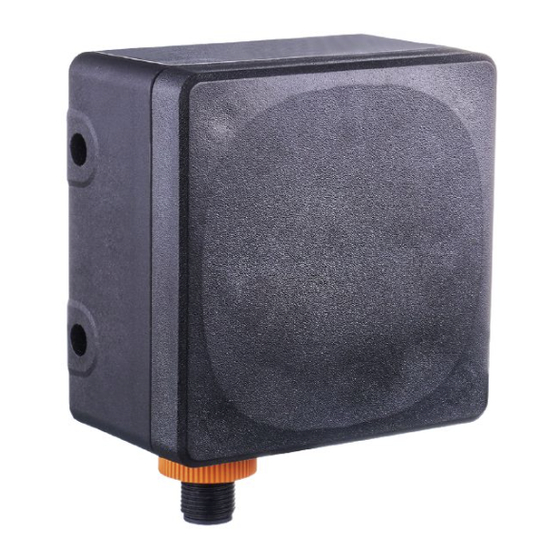
Radar area sensor with IO-Link R2Dx Vertical angle of aperture Horizontal angle of aperture 1: ± 25° 2: ± 70° 6.2 Mechanical design Fig. 2: Mechanical design Connection (can be rotated by 270°) Sensing face 6.3 Mounting with clamp u Insert the M5 screws through the through holes of the device and guide them into the threaded M5 holes of the bracket. -
Page 18: Mounting With Mounting Bracket
R2Dx Radar area sensor with IO-Link Fig. 3: Mounting M5 screws Through holes of the radar sensor Bracket Clamp M5 washers Fig. 4: Completed installation 6.4 Mounting with mounting bracket By means of the mounting bracket (E23009) the mounting angle of the sensor can be adjusted. A maximum angle of 45°... - Page 19 Radar area sensor with IO-Link R2Dx Fig. 5: Example By means of the mounting bracket (E23010) the mounting angle of the sensor can be adjusted. A maximum angle of 20° can be set. Fig. 6: Example...
-
Page 20: Electrical Connection
R2Dx Radar area sensor with IO-Link 7 Electrical connection The unit must be connected by a qualified electrician. Observe the national and international regulations for the installation of electrical equipment. Voltage supply according to SELV, PELV. u Disconnect power. u Connect the unit as follows: OUT2 OUT1/IO-Link Fig. 7: Wiring diagram (colours to DIN EN 60947-5-2) -
Page 21: Pnp/Npn Selection
Radar area sensor with IO-Link R2Dx Recommendation: Use pre-configured connection cables / sockets, see accessories at www.ifm.com. The device can be damaged by insufficiently tightened M12 connectors. The IP rating indicated in the data sheet is only guaranteed if the M12 connectors are firmly screwed. -
Page 22: Installation
R2Dx Radar area sensor with IO-Link 8 Installation To be able to make full use of the device’s functions, the ifm Vision Assistant software is required for parameter setting. u Go to the download section at this link and download the ifm Vision Assistant software onto your computer. -
Page 23: Operating And Display Elements
Status LED flashing red Error (correctable by the operator) Trou- (1 Hz) bleshooting (Ò / 29) Status LED is red Serious error u Contact ifm support. Contact at www.ifm.com Status LED is green, [Find me] function OUT1 and OUT2 (8 Hz) flashing... -
Page 24: Set-Up
After power on, the device is put into operation. After approx. 3 s the device is ready for operation. On delivery, the parameters are set to the factory setting. The device is configured via the ifm Vision Assistant or a suitable IO-Link software. -
Page 25: Parameter Setting
The device can be configured using the following options: • IO-Link software, e.g. ifm moneo configure SA • ifm Vision Assistant software (→ see software manual at www.ifm.com) The coordinate system The coordinate system is defined according to the right-hand rule. Fig. 10: Schematic illustration in the coordinate system... -
Page 26: R2D100/R2D102 Or R2D200/R2D202/R2D204
R2Dx Radar area sensor with IO-Link The z coordinate corresponds to the height, output above the sensor with a positive sign and below the sensor with a negative sign. The device comes with integrated inclination measurement and can output information on its inclination angle. - Page 27 Radar area sensor with IO-Link R2Dx Fig. 13: Top view X axis [m] Y axis [m] Object: pedestrian (-10 dB) Object: reflector 50 mm (0 dB) Object: passenger car (10 dB) -2,5 -7,5 Fig. 14: Side view Z axis [m] X axis [m] Object: pedestrian (-10 dB) Object: reflector 50 mm (0 dB) Object: passenger car (10 dB)
-
Page 28: R2D110/R2D111 Or R2D210/R2D211/R2D212
“On” if the sensing face of the sensor is blocked. The Vision Assistant displays the field of view and the range profile of the device. You can find the instructions for configuring the Vision Assistant at www.ifm.com (Ò software manual). 11.2 R2D110/R2D111 or R2D210/R2D211/R2D212 Angle of aperture (Ò... -
Page 29: Troubleshooting
Adjust supply voltage Supply voltage outside the specification (Ò technical data sheet) If the device behaves unexpectedly or incorrectly: u Download and install the latest firmware and ifm Vision Assistant versions (Ò Installation / 22). Download at documentation.ifm.com. u Disconnect the device from the voltage supply (restart) u Restore factory settings, i.e. -
Page 30: Maintenance, Repair And Disposal
R2Dx Radar area sensor with IO-Link 13 Maintenance, repair and disposal If used correctly, the unit is maintenance-free. u Keep the sensing face and any clear spaces free from deposits and foreign bodies. u It is not possible to repair the unit. Only the manufacturer is allowed to repair the unit. -
Page 31: Approvals / Standards
Radar area sensor with IO-Link R2Dx 14 Approvals / standards For approvals and standards, the following information is available: • Test standards and regulations: documentation.ifm.com • EU declaration of conformity and approvals: documentation.ifm.com • Notes relevant for approval: Package insert of the device and documentation.ifm.com... -
Page 32: Factory Setting
R2Dx Radar area sensor with IO-Link 15 Factory setting The factory settings of the parameters are available at documentation.ifm.com (PDF – IO-Link interface description). -
Page 33: Glossary
Radar area sensor with IO-Link R2Dx Glossary RCS stands for Radar Cross Section (radar signature) and is a measure of how well a target is detectable by radar, i.e. how much of the emitted energy is reflected from a target. The higher the RCS value, the better the reflectivity and thus the visibility of the target.
Need help?
Do you have a question about the R2D Series and is the answer not in the manual?
Questions and answers