Sign In
Upload
Download
Table of Contents
Contents
Add to my manuals
Delete from my manuals
Share
URL of this page:
HTML Link:
Bookmark this page
Add
Manual will be automatically added to "My Manuals"
Print this page
×
Bookmark added
×
Added to my manuals
Manuals
Brands
IFM Manuals
Security Sensors
PN2090
Operating instructions manual
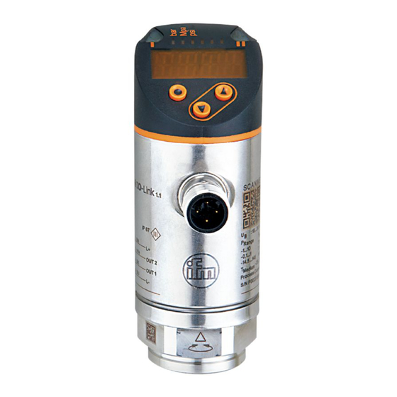
IFM PN2090 Operating Instructions Manual
Electronic pressure sensor
Hide thumbs
1
Table Of Contents
2
3
4
5
6
7
8
9
10
11
12
13
14
15
16
17
18
19
20
21
22
23
24
25
26
27
28
29
page
of
29
Go
/
29
Contents
Table of Contents
Bookmarks
Table of Contents
Table of Contents
Preliminary Note
1�1 Symbols Used
Safety Instructions
Functions and Features
3�1 Applications
Function
4�1 Operating Modes
4�2 Communication, Parameter Setting, Evaluation
4�3 Switching Function
4�4 Analogue Function
4�5 IO-Link
4�5�1 General Information
4�5�2 Functions Only Available Via IO-Link Communication
Installation
Electrical Connection
Operating and Display Elements
Menu
8�1 Menu Structure: Main Menu
8�2 Explanation of the Menu
8�2�1 Explanation of Menu Level 1
8�2�2 Explanation of Menu Level 2
Parameter Setting
9�1 Parameter Setting in General
9�2 Define Operating Mode (Optional)
9�3 Configure Display (Optional)
9�4 Set Output Signals
9�4�1 Set Output Functions
9�4�2 Define Switching Limits for the Hysteresis Function
9�4�3 Define Switching Limits for the Window Function
9�4�4 Scale Analogue Value
9�5 User Settings (Optional)
9�5�1 Set Delay Time for the Switching Outputs
9�5�2 Set Output Logic for the Switching Outputs
9�5�3 Set Damping for the Switching Signal
9�5�4 Set Damping for the Analogue Output
9�5�5 Zero-Point Calibration
9�5�6 Reset All Parameters to Factory Setting
9�5�7 Set Colour Change of the Display
9�5�8 Graphical Depiction of the Colour Change of the Display
9�6 Diagnostic Functions
9�6�1 Read Min/Max Values for the System Pressure
Operation
10�1 Read Set Parameters
10�2 Self-Diagnostics / Fault Indications
Technical Data
11�1 Setting Ranges
11�1�1 Setting Ranges in Operating Mode 2
11�1�2 Setting Ranges in Operating Mode 3
Factory Setting
Advertisement
Quick Links
Download this manual
Operating instructions
Electronic pressure sensor
UK
UK
PN2090
PN2091
Table of
Contents
Previous
Page
Next
Page
1
2
3
4
5
Advertisement
Table of Contents
Need help?
Do you have a question about the PN2090 and is the answer not in the manual?
Ask a question
Questions and answers
Subscribe to Our Youtube Channel
Related Manuals for IFM PN2090
Security Sensors IFM PI1689 Operating Instructions Manual
Electronic pressure sensor (21 pages)
Security Sensors IFM PI299 Series Operating Instructions Manual
Electronic pressure sensor (21 pages)
Security Sensors IFM PN2091 Operating Instructions Manual
Electronic pressure sensor (29 pages)
Security Sensors IFM PN701 Series Operating Instructions Manual
Electronic pressure sensor (29 pages)
Security Sensors IFM PN7032 Operating Instructions Manual
Electronic pressure sensor (29 pages)
Security Sensors IFM PN7034 Operating Instructions Manual
Electronic pressure sensor (29 pages)
Security Sensors IFM PN7191 Operating Instructions Manual
Electronic pressure sensor (27 pages)
Security Sensors IFM PI1694 Operating Instructions Manual
Electronic pressure sensor (21 pages)
Security Sensors IFM PI1695 Operating Instructions Manual
Electronic pressure sensor (21 pages)
Security Sensors IFM PI1697 Operating Instructions Manual
Electronic pressure sensor (21 pages)
Security Sensors IFM PI1698 Operating Instructions Manual
Electronic pressure sensor (21 pages)
Security Sensors IFM PQS Series Operating Instructions Manual
Electronic pressure sensor (57 pages)
Security Sensors IFM PI7993 Operating Instructions Manual
Electronic pressure sensor (19 pages)
Security Sensors IFM PQC Series Operating Instructions Manual
Electronic pressure sensor (58 pages)
Security Sensors IFM PV70 Series Operating Instructions Manual
Electronic pressure sensor for industrial applications (11 pages)
Security Sensors IFM UGT592 Operating Instructions
Ultrasonic diffuse-reflection sensor with io-link (5 pages)
This manual is also suitable for:
Pn2091
Table of Contents
Print
Rename the bookmark
Delete bookmark?
Delete from my manuals?
Login
Sign In
OR
Sign in with Facebook
Sign in with Google
Upload manual
Upload from disk
Upload from URL


Need help?
Do you have a question about the PN2090 and is the answer not in the manual?
Questions and answers