Table of Contents
Advertisement
Quick Links
Advertisement
Table of Contents

Subscribe to Our Youtube Channel
Related Manuals for IFM LK31 Series


Summary of Contents for IFM LK31 Series
- Page 1 Operating instructions Electronic level sensor LK31xx...
-
Page 2: Table Of Contents
Contents 1 Preliminary note ���������������������������������������������������������������������������������������������������4 1�1 Symbols used ������������������������������������������������������������������������������������������������4 2 Safety instructions �����������������������������������������������������������������������������������������������4 3 Functions and features ����������������������������������������������������������������������������������������5 3�1 Application area ��������������������������������������������������������������������������������������������5 3�2 Restriction of the application area ����������������������������������������������������������������5 4 Getting started �����������������������������������������������������������������������������������������������������6 4�1 Example configuration 1 ��������������������������������������������������������������������������������6 4�2 Example configuration 2 ��������������������������������������������������������������������������������7 5 Function ���������������������������������������������������������������������������������������������������������������8 5�1 Measuring principle ��������������������������������������������������������������������������������������8 5�2 Operating principle / features of the unit ��������������������������������������������������������9... - Page 3 9�1 Menüstruktur ������������������������������������������������������������������������������������������������23 10 Parameter setting ��������������������������������������������������������������������������������������������24 10�1 Parameter setting in general ���������������������������������������������������������������������24 10�2 Basic settings �������������������������������������������������������������������������������������������25 10�2�1 Set unit of measurement [uni] �����������������������������������������������������������25 10�2�2 Set offset [OFS] ��������������������������������������������������������������������������������25 10�2�3 Set medium [MEdI] ���������������������������������������������������������������������������25 10�2�4 Set overflow prevention [OP] ������������������������������������������������������������26 10�2�5 Adjust overflow prevention [cOP] ������������������������������������������������������26 10�3 Set output signals ��������������������������������������������������������������������������������������28 10�3�1 Set output function [ou1] for OUT1 (switching output) ����������������������28...
-
Page 4: Preliminary Note
1 Preliminary note 1.1 Symbols used ► Instructions > Reaction, result […] Designation of keys, buttons or indications → Cross-reference Important note Non-compliance may result in malfunction or interference� Information Supplementary note� 2 Safety instructions • The device described is a subcomponent for integration into a system� - The manufacturer of the system is responsible for the safety of the system�... -
Page 5: Functions And Features
• Installation, electrical connection, set-up, operation and maintenance of the product must be carried out by qualified personnel authorised by the machine operator� • Protect units and cables against damage� • The unit complies with the standard EN 61000-6-4� The unit may cause radio interference in domestic areas�... -
Page 6: Getting Started
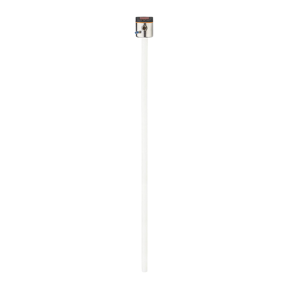
4 Getting started For fast set-up, the example configurations described in the following can be used for most applications� The indicated minimum distances apply exclusively to each separately described case� 4.1 Example configuration 1 Unit LK3122 (probe length L= 264 mm) Medium to be detected: mineral oil Operating mode:... -
Page 7: 4�2 Example Configuration 2
4.2 Example configuration 2 Unit LK3123 (probe length L= 472 mm) Medium to be detected: coolant emulsion Operating mode: automatic medium detection ((→ 5.2.1)) Installation environment: metal tank, installation to Fig� 4-2 Fig. 4-2 ► Install unit� ► Observe the distances (x), (u) and (c): min�... -
Page 8: Function
5 Function 5.1 Measuring principle The sensor determines the level according to the capacitive measuring principle: • An electrical field [E] is generated Fig. 5-1 and influenced by the medium to be detected� This change to the field causes a measurement signal that is electronically evaluated�... -
Page 9: 5�2 Operating Principle / Features Of The Unit
5.2 Operating principle / features of the unit The unit can be installed in tanks of different sizes� Mounting elements may also be placed in the active measurement zone� Observe the notes on installation� 2 outputs are available� They can be set separately� OUT1 switching signal for level limit / IO-Link OUT2... -
Page 10: 5�2�2 Notes On The Integrated Overflow Prevention
5.2.2 Notes on the integrated overflow prevention With the parameter [OP] (OP = overflow prevention), one of the upper measuring segments is defined as integrated overflow prevention OP� • If the overflow prevention OP is activated, an adjustment to the installation situation has to be made [cOP]�... -
Page 11: 5�4 Analogue Functions
5.4 Analogue functions The unit provides an analogue signal proportional to level� The analogue output (OUT2) can be configured: • [ou2] defines the output function of the analogue output: mA / V, (→ 10.3.2)� • In case of an internal fault, the output signal reacts according to the parameters set in [FOU2] (→... - Page 12 [OP] = [value ���] (overflow prevention OP activated) [ou2] = [InEG] or [UnEG] Fig. 5-4 Fig. 5-5 OP positioned in the upper segment OP shifted downward I [mA] / U [V] I [mA] / U [V] 20 / 10 20 / 10 4 / 0 4 / 0 A: active zone...
-
Page 13: 5�4�2 Curve Of The Analogue Signal Without Overflow Prevention
5.4.2 Curve of the analogue signal without overflow prevention [MEdI] = [Auto] or [OP] = [OFF] (overflow prevention OP deactivated) Fig. 5-6 Fig. 5-7 [ou2] = [I] or [U] [ou2] = [InEG] or [UnEG] I [mA] / U [V] I [mA] / U [V] I [mA] / U [V] I [mA] / U [V] 20 / 10... -
Page 14: 5�5 Switching Functions
5.5 Switching functions The unit signals via the switching output OUT1 that a set limit has been exceeded or that the level is below the limit� Selectable switching functions: • hysteresis function / normally open (Fig� 5-8): [ou1] = [Hno]� •... -
Page 15: 5�6 Offset For Indicating The Real Level In The Tank
In addition, communication is possible via a point-to-point connection with a USB adapter cable� The IODDs necessary for the configuration of the unit, detailed information about process data structure, diagnostic information, parameter addresses and the necessary information about the required IO-Link hardware and software can be found at www�ifm�com�... -
Page 16: Installation
6 Installation Fig. 6-1 probe length u ��� y: minimum distances zone for mounting elements overflow prevention maximum outside length metal object inside the tank Table 6-1 LK3122 LK3123 LK3124 [cm] [inch] [cm] [inch] [cm] [inch] L (rod length) 26�4 10�4 47�2 18�6... -
Page 17: Prevention
6.1 Installation instructions for operation with overflow prevention [MEdI] = [CLW��] or [OIL��] [OP] = [value ���] (overflow prevention OP activated) It is permitted to fix the mounting elements within the mounting zone (M) (Fig� 6-1)� ► Adhere to the maximum permitted outside length (c) (Table ►... -
Page 18: 6�2 Installation Instructions For Operation Without Overflow Prevention
6.2 Installation instructions for operation without overflow prevention [MEdI] = [Auto] or [OP] = [OFF] (overflow prevention OP deactivated) 6.2.1 Installation in the inactive zone Between the maximum level (b1) and the inactive zone (I1), the minimum distance (a1) has to be adhered to (Fig� 6-2 and table 6-3)� 6-3)! ►... -
Page 19: 6�2�2 Installation In The Active Zone
6.2.2 Installation in the active zone The minimum distance (a2) has to be observed between the maximum level (b2) and the mounting element (Fig� 6�3 and Table 6-4)! ► Fix mounting elements in the mounting Fig. 6-3 zone (M) (Fig� 6-1)� Adhere to the maximum permitted outside length (c) (Table 6-1 )�... -
Page 20: 6�3 Other Installation Notes
In case of automatic medium detection [MEdI] = [Auto] or deactivated overflow prevention [OP] = [OFF], the sensor reinitialises itself each time it is switched on and makes adjustments to the medium and the installation environment� The active zone / measuring range must not be completely covered by the medium�... -
Page 21: Electrical Connection
7 Electrical connection The unit must be connected by a qualified electrician� The national and international regulations for the installation of electrical equipment must be adhered to� Voltage supply according to EN 50178, SELV, PELV� ► Disconnect power� ► Connect the unit as follows: Core colours black OUT2... -
Page 22: Operating And Display Elements
8 Operating and display elements 3 4 5 6 Mode/Enter 1 to 8: Indicator LEDs LED 1 indication in centimetres LED 2 indication in inches LEDs 3���7 not used LED 8 switching status OUT1 (on if output 1 is switched) 9: [Mode/Enter] button - selection of the parameters and acknowledgement of the parameter values 10: [Set] button... -
Page 23: Menu
9 Menu 9.1 Menüstruktur - - - - 20.0 10.0 19.5 MEdl CLW.1 20.4 donE FOU1 FOU2 Menu items highlighted in grey, e�g� [ cOP ], are only active when assigned parameters have been selected�... -
Page 24: Parameter Setting
10 Parameter setting 10.1 Parameter setting in general ► Press [Mode/Enter] until the required parameter is displayed� To select parameters in the extended Mode/Enter Set menu (menu level 2): ► Select [EF] and briefly press [Set]� ► Press and hold [Set]� >... -
Page 25: 10�2 Basic Settings
The unit can be configured before or after installation� Exception: To adjust the overflow prevention [cOP], the unit must be installed in the tank� 10.2 Basic settings Setting ranges of all parameters: (→ 13) Factory settings of all parameters: (→ 15) 10.2.1 Set unit of measurement [uni] ►... -
Page 26: 10�2�4 Set Overflow Prevention [Op]
The settings [CLW�1] and [CLW�2] suppress deposits (e�g� metal swarf)� The settings [OIL�1] and [OIL�2] suppress a bottom layer of higher dielectric water or swarf which is a few cm high� If no oil layer is present (or if it is very thin), the bottom layer is detected�... - Page 27 ► Select [cOP]� ► Press [SET] and keep it pressed� > [cOP] flashes for some seconds; then the continuous display indicates that the adjustment is being made� > If the adjustment is successful, [donE] is displayed� ► Confirm with [Mode/Enter]� >...
-
Page 28: 10�3 Set Output Signals
10.3 Set output signals 10.3.1 Set output function [ou1] for OUT1 (switching output) ► Select [ou1] and set the switching function: [Hno] = hysteresis function / normally open [Hnc] = hysteresis function / normally closed [Fno] = window function / normally open [Fnc] = window function / normally closed If the switching output is used as an overflow prevention, the setting [ou1] = [Hnc] (normally closed function) is recommended�... -
Page 29: 10�3�5 Set Switching Delay [Ds1] For The Switching Output
10.3.5 Set switching delay [dS1] for the switching output ► Select [dS1] and set the value between 0�0 and 60 s� The switching delay reacts according to VDMA� 10.3.6 Set switch-off delay [dr1] for switching output ► Select [dr1] and set the value between 0�0 and 60 s� The switching delay reacts according to VDMA�... -
Page 30: Notes On Parameter Setting Via Io-Link
11 Notes on parameter setting via IO-Link On delivery the LK31xx-type unit is not operational� First, the integrated overfill prevention OP has to be adjusted� Depending on the application, OP adjustment can be carried out in diffe- rent ways: • directly on the display (→ 10)� •... -
Page 31: Operation
12 Operation After switch-on of the operating voltage, the unit is in the operating mode (= nor- mal operating mode)� It carries out its measurement and evaluation functions and generates output signals according to the set parameters� ► Check whether the unit operates correctly� 12.1 Operation indication Table 11-1 [----] (continuous) -
Page 32: 12�3 Error Indications
12.3 Error indications Table 11-2 Possible cause Recommended measures [Err] Fault in the electronics ► Replace the unit� • Interfering sources (e�g� EMC) ► Check electrical connection� [SEnS] • Poor cables ► Check connection between the • Supply voltage disturbed sensor and the tank ground�... -
Page 33: Technical Data
13 Technical data Technical data and scale drawing at www�ifm�com� 13.1 Setting values [OFS] Table 12-1 [cm] [inch] Setting range 0���200�0 0���78�8 LK3122 LK3122 LK3124 LK3124 LK3123 LK3123 Step increment 0�5 0�2 0�5 13.2 Setting values [OP] Table 12-2 LK3122... -
Page 34: 13�3 Calculation Aids
The indicated values for [OP] refer to the distance between OP and the lower edge of the probe� The values apply if [OFS] = [0]� If [OFS] > [0] the values increase by the set OFS value� Example LK3122: According to Table 12-2, OP is set to segment 20�4� [OFS] = 7�0 cm [OP] is to be set to 20�4 cm + 7�0 cm = 27�4 cm�... -
Page 35: 13�3�2 Definition "From The Bottom
13.3.2 Definition "from the bottom" Response level (z) of the overflow prevention OP from the tank bottom is defined� • Without offset ([OFS] = [0]): [OP] = z - u • With offset ([OFS] = u): [OP] = z Example: z = 18�0 cm (from the tank bottom), u = 1�0 cm Without offset: [OP] = 18�0 cm - 1�0 cm = 17�0 cm With offset: [OP] = 18�0 cm... -
Page 36: Maintenance / Cleaning / Change Of Medium
14 Maintenance / cleaning / change of medium When removing or installing the unit for maintenance and cleaning: ► Make sure that the stainless steel tube clip is fixed to the sensor� > It must be possible to exactly reproduce the installation height and position! ►... -
Page 37: Factory Setting
15 Factory setting Factory setting User settings LK3122 LK3123 LK3124 20.0 39.0 19.5 38.5 20.4 40.7 MEdI CLW.1 ---- ---- FOU1 FOU2 More information at www�ifm�com...
Need help?
Do you have a question about the LK31 Series and is the answer not in the manual?
Questions and answers