Table of Contents
Advertisement
Quick Links
Advertisement
Table of Contents

Related Manuals for IFM PQC Series


Summary of Contents for IFM PQC Series
- Page 1 Operating instructions Electronic pressure sensor PQCxxx...
-
Page 2: Table Of Contents
PQCxxx Electronic pressure sensor Contents Preliminary note ............. Symbols used . - Page 3 Electronic pressure sensor PQCxxx 10.7.3 Binary data transmission (BLOB) ........50 10.7.5 Lock / unlock .
-
Page 4: Preliminary Note
PQCxxx Electronic pressure sensor 1 Preliminary note You will find instructions, technical data, approvals and further information using the QR code on the unit / packaging or at documentation.ifm.com. 1.1 Symbols used Requirement Instructions Reaction, result [...] Designation of keys, buttons or indications... -
Page 5: Safety Instructions
Electronic pressure sensor PQCxxx 2 Safety instructions • The unit described is a subcomponent for integration into a system. – The system architect is responsible for the safety of the system. – The system architect undertakes to perform a risk assessment and to create documentation in accordance with legal and normative requirements to be provided to the operator and user of the system. -
Page 6: Intended Use
PQCxxx Electronic pressure sensor 3 Intended use The unit measures and monitors the system pressure of machines and installations. 3.1 Application area Type of pressure: relative pressure CAUTION Static and dynamic overpressure w Destruction of the device even if the indicated bursting pressure is exceeded only for a short time. -
Page 7: Function
IO-Link is a communication system for connecting intelligent sensors and actuators to automation systems. IO-Link is standardised in the IEC 61131-9 standard. General information on IO-Link at io-link.ifm Input Output Device Description (IODD) with all parameters, process data and detailed descriptions of the device at documentation.ifm.com... - Page 8 PQCxxx Electronic pressure sensor • Automatic backup and restore of parameter sets in case of device replacement (data storage) • Logging of parameter sets, process values and events • Device description file (IODD - Input Output Device Description) for easy project planning •...
-
Page 9: Installation
This means that the device can be screwed into the process facing backwards or downwards. The unused device connection is covered with a sealing plug. Integrated process connection at the rear (threaded connection Ò data sheet under documentation.ifm.com) Process connection at the bottom (threaded connection Ò data sheet under documentation.ifm.com) On delivery, a sealing plug is screwed into the rear process connection. -
Page 10: Connection As Pneumatic Distributor
PQCxxx Electronic pressure sensor • Make sure the seal is seated correctly. • Maximum tightening torque: 0.8 Nm. u Screw the pressure connection of the process or adapter into the process connection of the device and tighten it. • Maximum tightening torque: 8 Nm. •... -
Page 11: Installation Examples
Electronic pressure sensor PQCxxx 5.2 Installation examples 5.2.1 Installation on a pipe Fig. 3: Installation on a pipe 5.2.2 Maintenance unit Fig. 4: Maintenance unit 5.2.3 Wall mounting The device is fixed to the rear panel using two M3 x 8 mm cylinder screws (included). u Prepare two M3 internal threads with the following dimensions in the rear panel:... - Page 12 PQCxxx Electronic pressure sensor 20 ± 1 Fig. 5: Prepare rear panel u Screw the cylinder screws into the panel until the screw heads stick out approx. 4 mm from the panel. u Place the device and push it downwards until it locks into place: Fig. 6: Place device u Tighten the cylinder screws alternately until the device is flush with the rear panel.
-
Page 13: Rear Wall Mounting With Mounting Bracket
5.2.4 Rear wall mounting with mounting bracket The device can be attached to a rear wall using a mounting bracket. Information about available accessories at www.ifm.com u Hold the mounting bracket to the rear wall and mark the position of the drill holes: •... - Page 14 Fig. 10: Rear wall mounting with multiple mounting brackets 5.2.5 Table mounting The device can be attached to a table top using a mounting bracket. Information about available accessories at www.ifm.com u Prepare three drill holes in the table top: • Two drill holes for the lower pins (2) at a distance of 20 mm and with a diameter of 4 mm.
-
Page 15: Din Rail Mounting
5.2.6 DIN rail mounting The device can be attached to a DIN rail using a mounting bracket. Information about available accessories at www.ifm.com u Hook the device into a 35 mm DIN rail and clip it into place. u Place the device onto the attachment pins (1) of the mounting bracket and push it downwards until... -
Page 16: Panel Mounting
The device can be installed in a panel using a mounting set. The mounting set is not supplied with the device. Information about available accessories at www.ifm.com u In a panel with a maximum thickness of 6 mm, make a 31 mm x 31 mm cutout (-0.4 mm tolerance each). - Page 17 Electronic pressure sensor PQCxxx u Slide the fixing clamp of the mounting set onto the device from behind. The locating lugs of the fixing clamp (4) will latch in the jagged recesses on both sides of the device (5). Push until the device is firmly in place.
- Page 18 ≤ R1,5 (4x) Fig. 18: Horizontal installation for devices with M8 connector; n = number of devices The dimensions apply to the use of ifm connectors with angled M8 sockets. If straight cable sockets are used, the distance must be increased.
-
Page 19: Electrical Connection
Electronic pressure sensor PQCxxx 6 Electrical connection The unit must be connected by a qualified electrician. Observe the national and international regulations for the installation of electrical equipment. Voltage supply according to SELV, PELV. u Disconnect power. u Connect the unit as follows: OUT2 OUT1/ IO-Link Fig. 20: Wiring diagram (colours to DIN EN 60947-5-2) -
Page 20: Operating And Display Elements
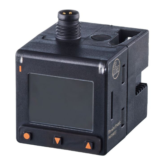
PQCxxx Electronic pressure sensor 7 Operating and display elements Switching status LED for OUT1 (on if output 1 is active) TFT display 2a: Title line 2b: Process value line 2c: Additional information depending on the setting of [dis.L] (Ò Display layout / 41) Keys for display change and parameter setting (Ò... -
Page 21: Menu
Electronic pressure sensor PQCxxx 8 Menu The figures in which the menus are displayed show the parameters that can be set on the unit by key input. These parameters and other functions are also available via the IO-Link interface. Process value display Main menu Extended functions [EF] Basic settings [CFG]... - Page 22 PQCxxx Electronic pressure sensor Main menu: Process value display Single point Two point Window Deactivated SSC1.1-SP1 SSC1.1-SP1 SSC1.1-SP1 SSC1.1-HYS SSC1.1-SP2 SSC1.1-SP2 SSC1.1-HYS ASP2 AEP2 [EF] BACK Parameter Explanation SSC1.1-SP1 Switch point 1 for switching signal channel SSC1.1 SSC1.1-SP2 Switch point 2 for switching signal channel SSC1.1 SSC1.1-HYS Hysteresis for switching signal channel SSC1.1 ASP2...
- Page 23 Electronic pressure sensor PQCxxx Configuration [CFG] menu: Main menu [EF] uni.P kPa│MPa│mbar│bar│psi inHg│mmHg│kgf/cm │% dAP.P ---- OUT1 PnP│nPn OUT2 ---- tcOF No │Yes Guide No │Yes Back DevInfo [CFG] Back * The choice of units depends on the device type. See Standard unit of measurement (Ò / 38).
- Page 24 PQCxxx Electronic pressure sensor Menu Output configuration [OUT1]: SSC1.1│OFF Main menu LOGI High│Low [EF] modE Two Point│Deactiv.│Single pt.│Window TCH1 No│Yes OUT1 ---- OUT2 TCH2 No│Yes ---- ---- ---- DevInfo ---- Back Back [OUT1] Parameter Explanation OUT1 Change to submenu OUT1 (output configuration of output 1) Output function for output OUT1 LOGI Switch-point logic: [high active] or [low active]...
- Page 25 Electronic pressure sensor PQCxxx Menu Output configuration [OUT2]: Main menu [EF] I │U5│U10│I │U5 │U10 │OFF ASP2 ---- OUT1 AEP2 ---- OUT2 ---- Back [OUT2] DevInfo Back Parameter Explanation OUT2 Change to submenu OUT2 (output configuration of output 2) Output function for output OUT2 ASP2 Analogue start point for OUT2 AEP2...
- Page 26 PQCxxx Electronic pressure sensor Display menu [DIS]: Main menu [EF] LanG DE│EN│FR│ES│IT│PT│ZH│JA│KO diS.R 0°│180° OUT1 diS.B 25│50│75│100│OFF OUT2 diS.L PV│SP1│SP2│BGrp│sC.1│Hi.P│Lo.P BGrp.S ---- BGrp.E ---- coL.P W/B│G1OU│r1OU DevInfo diS.U d1│d2│d3 Back Back [DIS] Parameter Explanation Change to the DIS (display) submenu. LanG Language selection for the display diS.R...
- Page 27 Electronic pressure sensor PQCxxx Diagnostics [DIA] menu: Main menu [EF] OUT1 OUT2 Lo.P ----│Reset Hi.P ----│Reset Operh ---- DevInfo sC.1 ----│Reset Back Back [DIA] Parameter Explanation Change to the submenu DIA (diagnostics) Lo.P Lowest pressure value measured Hi.P Maximum pressure value measured Operh Operating hours since first set-up sC.1...
- Page 28 PQCxxx Electronic pressure sensor Simulation [SIM], Device information [DevInfo] and Reset device [rES] menu: S.PRES ----│OL│UL*│Err Main menu S.Tim 1│2│3│4│5│10│15│20│30│45│60 S.On OFF│ON [EF] Back [SIM] OUT1 OUT2 [DevInfo] DevInfo APPL No│Yes Back No│Yes Back [rES] Parameter Explanation Change to the submenu SIM (simulation) S.PRS Simulated pressure value in simulation mode S.Tim...
-
Page 29: Commissioning
Electronic pressure sensor PQCxxx 9 Commissioning After power on and expiry of the power-on delay time, the unit is in the normal operating mode. It carries out its measurement and evaluation functions and generates output signals according to the set parameters. During the power-on delay time, the outputs are in the following status according to the set parameters: Switching output:... -
Page 30: Parameter Setting
Guided installation via an installation wizard (Ò / 29). 10.2 Parameter setting via IO-Link Requirements for parameter setting via the IO-Link interface: ü A suitable parameter setting software, e.g. ifm moneo|configure ü The Input Output Device Description (IODD) for the device, see documentation.ifm.com ü One IO-Link master u Connect the IO-Link master to a parameter setting software. -
Page 31: Output Configuration
Electronic pressure sensor PQCxxx u Connect the device to a free port of the IO-Link master. w The unit switches to IO-Link mode. u Change parameter settings in the software. u Write parameter settings to the unit. Notes on parameter setting Ò Manual of the parameter setting software 10.3 Output configuration 10.3.1 Digital switching signal The device provides digital switching signals via switching signal channels (SSC = Switching Signal... - Page 32 PQCxxx Electronic pressure sensor Deactivated If the [Deactivated] switch point mode is set for a switching signal channel, then the switching signal channel will permanently have the following value regardless of the process value: • For switch point logic [High active]: permanently “low”. •...
- Page 33 Electronic pressure sensor PQCxxx high high (TP2) (TP1) (TP2) (TP1) Fig. 27: [Two Point Mode] / [High active] Fig. 28: [Two Point Mode] / [Low active] SP1: Switch point 1 SP1: Switch point 1 SP2: Switch point 2 SP2: Switch point 2 TP1: Teach point 1 (= SP1) TP1:...
- Page 34 PQCxxx Electronic pressure sensor Measuring range Hysteresis [Single Point] Hysteresis [Window] -1…10 bar 0.2 bar 0.02 bar 0…16 bar 0.32 bar 0.03 bar Tab. 1: Hysteresis with [Auto] setting depending on the measuring range of the device and the selected switch-point mode 10.3.1.1 Parameter setting via device keys: Switching signal You can only set switching signal channel SSC1.1 via the device keys.
- Page 35 Electronic pressure sensor PQCxxx Two-point mode: u Select [modE] and set the switch-point mode: [Two Point]. u Approach the system pressure at which the output is to switch and keep it constant. u Select [TCH1] and set [Yes]. w The current value is adopted as switch point SP1. u Approach the system pressure at which the output is to reset and keep it constant.
-
Page 36: Analogue Signal
PQCxxx Electronic pressure sensor 10.3.1.4 Teach via IO-Link: Switching signal Both switching signal channels can be set via the IO-Link interface. ü The standard unit of measurement is selected: [Parameters] > [Basic settings] > [uni.P]. ü For output x, the switching signal is selected: [Parameters] > [Ausgangskonfiguration] > [oux] = [SSC1.x] ü... -
Page 37: Output Off
Electronic pressure sensor PQCxxx Besides, the analogue signal can be inverted (e.g. I = 4…20 mA and I = 20…4 mA). The analogue signal is set via the parameter [ou2] (Ò see table). The parameters [ASP2] and [AEP2] allow for the measuring range to be limited: •... -
Page 38: Application Configuration
PQCxxx Electronic pressure sensor 10.3.3.1 Parameter setting via device keys: Output off u Go to the [EF] > [OUTx] menu. u Select [oux] and set [OFF]. - or - u Select [modE] and set [Deactivated]. 10.3.3.2 Parameter setting via IO-Link: Output off u Call up [Parameters] >... -
Page 39: Damping
Electronic pressure sensor PQCxxx u Select [uni.P] and set the unit of measurement. u Select [uni.T] and set the unit of measurement. 10.4.2 Damping The set damping constant stabilises the output signals. Abrupt changes in the physical process values are smoothed out. This concerns the outputs, the display and the process value transmission via the IO-Link interface. -
Page 40: Zero Calibration
PQCxxx Electronic pressure sensor 10.4.3.2 Parameter setting via IO-Link: Output polarity u Select [Parameters] > [Basic settings]. u Select [P-n] and set [PnP] or [nPn]. 10.4.4 Zero calibration If there is a systematic deviation between the measured value and the actual process value, this measurement inaccuracy can be corrected using the correction factor [cOF] or [tcOF]. -
Page 41: Switch-Point Logic
Electronic pressure sensor PQCxxx u Select [cOF] and set the value. w The internal zero point is shifted by the set value. Teach zero point calibration: u Maintain the plant pressure constantly at 0. u Select [Parameter] > [Application]. u Execute command: [Teach tcoF]. w The current measured value is taken as internal zero point if the deviation lies within a range of ±5% of the final value of the measuring range. -
Page 42: Display Bar Graph Scaling
PQCxxx Electronic pressure sensor If PV is set, only the process value for pressure is displayed. For all other settings, additional information is displayed below the process value depending on the selection. SP1: 4 SP2: 6 sC.1 Hi.P Lo.P xxxxxxxxxxxxxxxxx Device keys IO-Link Description... -
Page 43: Display Update Rate
Electronic pressure sensor PQCxxx SP1: 5 SP2: 6 SP1: 5 SP2: 6 0 bar 16 bar 3 bar 8 bar Fig. 32: Scaling of the bar graph display Bar graph with factory setting*. Example: • [BGrp.S] = 0 bar = initial value of the measuring range MAW •... -
Page 44: Display Language
PQCxxx Electronic pressure sensor 10.5.4 Display language The display language can be set via the parameter [LanG]. Selectable languages: • DE: German • EN: English • FR: French • ES: Spanish • IT: Italian • PT: Portuguese • ZH: Chinese • JA: Japanese •... -
Page 45: Display Rotation
Electronic pressure sensor PQCxxx 10.5.5.2 Parameter setting via IO-Link: display brightness u Call up [Parameters] > [Display Setting]. u Select [diS.B] and set the brightness of the display. 10.5.6 Display rotation Use the parameter [diS.R] to rotate the text in the display clockwise for better readability. Selectable values: •... -
Page 46: Diagnostic Functions
PQCxxx Electronic pressure sensor Fig. 34: Colour change in [Window] mode; example: coLr = G1ou; normally open Selectable values: • [W/B]: The font colour is always white and the background black, regardless of the switching status. • [r1ou]: The display background changes from green to red. •... -
Page 47: Operating Hours Counter
Electronic pressure sensor PQCxxx 10.6.1.2 Reading via IO-Link: Memory u [Parameters] > Call up [memory] . u Select [Lo.P] or [Hi.P] and read the minimum or maximum stored process value. Clear memory: u [Parameters] > Call up [memory] . u Execute command: •... -
Page 48: Switching Cycles Counter
PQCxxx Electronic pressure sensor Clear memory: u Execute command: [Reset HIPC]. 10.6.4 Switching cycles counter The device stores the number of switching cycles of the two switching signal channels SSC1.1 and SSC1.2. The current value can be read from the unit’s display or via the IO-Link interface. In case of a voltage interruption, the events of the last 10 minutes can be lost. -
Page 49: Device Information
Electronic pressure sensor PQCxxx 10.7.1.1 Parameterisation via unit keys: Simulation u Go to the [EF] > [SIM] menu. u Select [S.PRS] and set the pressure value to be simulated or a diagnostic case (e.g. OL). u Select [S.Tim]and set the time of the simulation in minutes. u Select [S.On] and set the function: •... -
Page 50: Binary Data Transmission (Blob)
The device offers a function for reading binary data from the device as one large file (BLOB = Binary Large Object). The data is exported as a CSV file. This requires a software tool (e.g. ifm moneo) that supports the IO-Link BLOB interface. The CSV file contains the following logbook information: •... -
Page 51: Lock / Unlock
Electronic pressure sensor PQCxxx u Select [Identification]. u Execute command: [Locator Start]. u To end the flashing process: Execute command: [Locator Stop]. The flashing can also be stopped by pressing any key on the device. 10.7.5 Lock / unlock The unit can be locked electronically to prevent unauthorised setting. This lock prevents the settings from being changed via the keys on the unit. - Page 52 PQCxxx Electronic pressure sensor If IO-Link data storage is activated, this triggers a parameter update in the master. This writes the parameters configured in the master to the device again. An application reset may therefore be ineffective. [BtB] = Back to Box The following is reset: •...
-
Page 53: Operation
Electronic pressure sensor PQCxxx 11 Operation After power on and expiry of the power-on delay time, the unit is in the normal operating mode. It carries out its measurement and evaluation functions and generates output signals according to the set parameters. Use the device keys to view additional information during operation: u Press the [▲] or [▼] key repeatedly. -
Page 54: Troubleshooting
Warnings and error states are displayed even if the display is switched off. If several diagnostic events occur simultaneously, only the diagnostic message of the event with the highest priority is displayed. Additional diagnostic functions are available via IO-Link Ò IO-Link interface description at documentation.ifm.com. 12.1 Warning messages Display LED*... -
Page 55: Error Messages
Electronic pressure sensor PQCxxx 12.2 Error messages Display Problem Corrective measures u Check/correct supply Display off. Supply voltage too low. voltage. u Allow the device to cool Display off. Internal device temperature over 97 °C. down. u Activation by key touch. The outputs are switched off. w Title line: Temperature error w After 10 s of inactivity, the Internal device temperature... -
Page 56: Maintenance, Repair And Disposal
PQCxxx Electronic pressure sensor 13 Maintenance, repair and disposal The operation of the unit is maintenance-free. Only the manufacturer is allowed to repair the unit. u After use dispose of the device in an environmentally friendly way in accordance with the applicable national regulations. -
Page 57: Factory Setting
14 Factory setting Parameter Factory setting User settings uni.P Depends on device type (Ò technical da- ta at www.ifm.com): MPa, kPa, bar, mbar, psi, inHg, mmHg, kgf/cm², % Depends on device type (Ò technical da- ta at www.ifm.com) dAP.P 0.06 S.Tim S.On... - Page 58 PQCxxx Electronic pressure sensor Parameter Factory setting User settings OUT2 Measuring range -1…0 bar (20…4 mA) -1…1 bar I (4...20 mA) -1…10 bar I (4...20 mA) 0…16 bar I (4...20 mA) ASP2 Measuring range ASP2 -1…0 bar -1 bar -1…1 bar -1 bar -1…10 bar -1 bar...
Need help?
Do you have a question about the PQC Series and is the answer not in the manual?
Questions and answers