Table of Contents
Advertisement
Quick Links
Advertisement
Table of Contents

Related Manuals for IFM PI7993


Summary of Contents for IFM PI7993
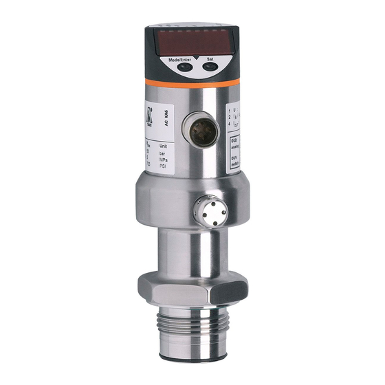
- Page 1 Operating instructions Electronic pressure sensor PI7993...
-
Page 2: Table Of Contents
Contents 1 Preliminary note ���������������������������������������������������������������������������������������������������3 1�1 Symbols used ������������������������������������������������������������������������������������������������3 2 Safety instructions �����������������������������������������������������������������������������������������������3 3 Functions and features ����������������������������������������������������������������������������������������4 3�1 Applications ���������������������������������������������������������������������������������������������������4 4 Function ���������������������������������������������������������������������������������������������������������������4 4�1 Processing of the measured signals ��������������������������������������������������������������4 4�2 Pressure monitoring / switching function �������������������������������������������������������5 4�3 Diagnostic function ����������������������������������������������������������������������������������������5 5 Installation������������������������������������������������������������������������������������������������������������6 6 Electrical connection ��������������������������������������������������������������������������������������������8 7 Operating and display elements ��������������������������������������������������������������������������9... -
Page 3: Preliminary Note
10�3 Cleaning of the filter cover �������������������������������������������������������������������������17 11 Factory setting �������������������������������������������������������������������������������������������������18 1 Preliminary note 1.1 Symbols used ► Instruction > Reaction, result […] Designation of buttons, switches or indications → Cross-reference Important note Non-compliance can result in malfunctions or interference� 2 Safety instructions •... -
Page 4: Functions And Features
• Installation, electrical connection, set-up, programming, configuration, operation and maintenance of the product must be carried out by personnel qualified and authorised for the respective activity� • Protect units and cables against damage� 3 Functions and features The pressure sensor detects the system pressure of machines and installations� 3.1 Applications Type of pressure: relative pressure Information on pressure rating and bursting pressure →... -
Page 5: 4�2 Pressure Monitoring / Switching Function
4.2 Pressure monitoring / switching function OUTx changes its switching state if it is above or below the set switching limits (SPx, rPx)� The following switching functions can be selected: • Hysteresis function / normally open: [OUx] = [Hno] (→ fig. 1). •... -
Page 6: Installation
5 Installation Ensure that no pressure is applied to the installation while mounting or removing the sensor� Please note: Display „0%“ does not mean that the system is free of pressure! Horizontal mounting recommended for high medium temperatures� ► Screw the sensor into a G ¾ process fitting�... - Page 7 Mounting ► Slightly grease the threads and sealing areas of the sensor and adapter with lubricating paste (C)� The paste must be suitable and approved for the application and compatible with the elastomers used� Recommendation: Klüber paste UH1 84-201 with USDA-H1 approval for the food industry�...
-
Page 8: Electrical Connection
Pin 4 (OUT1) • diagnostic output if [OU1] = [dESI] Pin 2 (OUT2) • binary switching output for pressure monitoring Core colours of ifm sockets: 1 = BN (brown), 2 = WH (white), 3 = BU (blue), 4 = BK (black) -
Page 9: Operating And Display Elements
7 Operating and display elements 3 4 5 6 Mode/Enter 1 to 8: Indicator LEDs - LED 1 to LED 6 = system pressure in unit of measurement as indicated on the label� LED 7, LED 8 = switching state of the respective output 9: Alphanumeric display, 4 digits - Indication of the current system pressure�... -
Page 10: Menu
8 Menu 8.1 Menu structure... -
Page 11: 8�2 Menu Explanation
8.2 Menu explanation SP1/rP1 Maximum / minimum value for system pressure, at which output 1 changes its switching status� Output function for OUT1: • Switching signal for the limit values: hysteresis function [H ��] or window function [F ��], normally open [� no] or normally closed [� nc] each� •... -
Page 12: Parameter Setting
9 Parameter setting During the parameter setting process the unit remains in the operating mode� It continues its monitoring function with the existing parameters until parameter setting has been terminated� 9.1 Parameter setting general Each parameter setting requires 3 steps: Selecting parameter ►... - Page 13 ► Press [Set] and keep it pressed until the valid code no� is displayed� ► Press [Mode/Enter] briefly� Delivery by ifm electronic: no access restriction� • Locking / unlocking The unit can be locked electronically to prevent unintentional wrong settings�...
-
Page 14: 9�2 Configuring The Display (Optional)
9.2 Configuring the display (optional) ► Select [Uni] and set the unit of measurement: - [bAr], [MPA], [PSI]� ► Select [SELd] and set the display mode: - [P]: Pressure in the unit set in Uni� - [P%]: percentage value (pressure in % of the set scaling of the analogue output�... -
Page 15: 9�3�2 Setting The Switching Limits
9.3.2 Setting the switching limits ► Select [SP1] / [SP2] and set the value at which the output switches� ► Select [rP1] / [rP2] and set the value at which the output switches back� rPx is always lower than SPx� The unit only accepts values which are lower than SPx�... -
Page 16: 9�4�4 Setting The Damping For The Switching Outputs
9.4.4 Setting the damping for the switching outputs ► Select [dAP] and set value between 0�1 and 100�0 s (at 0�0 = [dAP] is not active)� dAP value = response time between pressure change and change of the switching status in seconds� [dAP] influences the switching frequency: f = 1 ÷... -
Page 17: 10�2 Fault Indication
10.2 Fault indication [OL] Overload pressure (measuring range exceeded)� [UL] Underpressure range (measuring range below the minimum value)� [SC1] Short circuit in OUT1�* [SC2] Short circuit in OUT2�* [SC] Short circuit in both switching outputs�* [Err] Internal fault, invalid input� *The output concerned is switched off as long as the short circuit exists�... -
Page 18: Factory Setting
Factory setting User setting 25% VMR* 23% VMR* 75% VMR* 73% VMR* COF / tCOF SELd * = the indicated percentage of the final value of the measuring range (VMR) of the sensor in bar is set� More information at www�ifm�com...
Need help?
Do you have a question about the PI7993 and is the answer not in the manual?
Questions and answers