Table of Contents
Advertisement
NOT FOR RESIDENTIAL USE
•
Please read this manual and the enclosed safety materials completely, prior to installation and use!
•
This product is to be installed and serviced by a trained door systems technician ONLY.
•
These operators are compatible with myQ®, myQ® Smart Facility Access™, and Security+ 2.0®
accessories.
•
These operators are Wi-Fi® compatible.
2 YEAR WARRANTY
Serial #
Installation Date
Scan here for
LiftMaster support
videos and content.
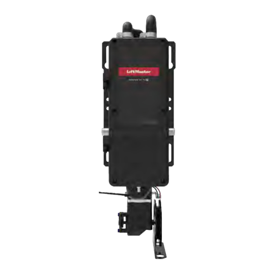
Industrial DC
Operators
Models JDC, JHDC, and
DC Jackshaft, Hoist, and Trolley
For Doors up to 700, 1200, and 2200 lbs
NOT FOR RESIDENTIAL USE
TDC
LiftMaster
300 Windsor Drive
Oak Brook, IL 60523
Advertisement
Table of Contents

Subscribe to Our Youtube Channel
Related Manuals for Chamberlain JDC


Summary of Contents for Chamberlain JDC
- Page 1 Industrial DC Operators Models JDC, JHDC, and DC Jackshaft, Hoist, and Trolley For Doors up to 700, 1200, and 2200 lbs NOT FOR RESIDENTIAL USE NOT FOR RESIDENTIAL USE • Please read this manual and the enclosed safety materials completely, prior to installation and use! •...
-
Page 2: Table Of Contents
Testing Jackshaft (JDC) and Hoist (JHDC) ..... . .7 Test all Entrapment Protection Devices ....27 TDC Trolley . -
Page 3: Safety Information
Safety Information Safety Symbol and Signal Word Review WARNING IMPORTANT NOTES: • BEFORE attempting to install, operate or maintain the commercial door operator, you must read and Mechanical fully understand this manual and follow all safety instructions. WARNING • DO NOT attempt repair or service of a commercial door operator unless you are an Authorized Service Technician. -
Page 4: Planning
Planning NOTE: Please obtain the latest Installation Manual by search the model number at liftmaster.com. SECTIONAL DOORS Recommended Drum/Sprocket Configuration for 12"/second Door Speed Operator Door Type Drum* Sprockets** Standard D400-96 Hi-lift D400-54 Standard D400-144 Vertical D850-132 Standard D5250-18 1200 Hi-lift D525-54 Hi-lift... -
Page 5: Introduction
Introduction Voltage Selection Voltage Selection 120/240V single and 3 phase dedicated sku 480V 3 phase dedicated sku 208V 3 phase Via accessory step down transformer 600V 3 phase Via accessory step down transformer Model Electrical Ratings Model Operator Type Electrical Rating Cycle Max. -
Page 6: Operator Specifications
• Model JDC: 12" per second for sectional and 8-9" Operation Mode: C2 (Factory default), B2, B2/T, B2/TS, D1, E2 and FSTS. per second for rolling steel doors. -
Page 7: Operator Dimensions
Operator Dimensions Jackshaft (JDC) and Hoist (JHDC) -
Page 8: Tdc Trolley
Operator Dimensions (continued) TDC Trolley 11.73" (29.8 cm) *Door Height Plus C (minimum) 4" (10.16 cm) 10.5" Highest Point of Door Travel (26.67 cm) OPERATOR DIMENSIONS TABLE DIMENSIONS 700LB STD 18.552" 21.065" 4 ft (1.2 m) 1200LB STD 18.867" 21.380" 4.3 ft (1.3 m) 1200LB EXT 18.867"... -
Page 9: Battery Backup
Operator Dimensions (continued) Battery Backup 4.70" 7H Battery 4H Battery (11.9 cm) 4.70" 7.22" (11.9 cm) (18.4 cm) 6.37" (16.2 cm) -
Page 10: Tdc Trolley Operators
TDC Trolley Operators WARNING To prevent possible SERIOUS INJURY or DEATH: • Disable ALL locks and remove ALL ropes connected to door BEFORE installing and operating door • DO NOT connect electric power until instructed to operator to avoid entanglement. do so. -
Page 11: Tdc Trolley Assembly
TDC Trolley Assembly HARDWARE Assemble the Operator Bolt 3/8"-16 Install the track spacers evenly over the length of the track. Fasten x 3/4" the spacers to the track with bolt (A) and flange hex nuts (B). Flange Hex Nut Spacers Provided Track Length 3/8"-16 8-14 foot... -
Page 12: Install The Chain
TDC Trolley Assembly (continued) Install the Chain The chain is packed separately from the operator. Please ensure you have your chain before starting installation. Position the trolley 2 inches (5.1 cm) away from the front idler. Attach the chain to the trolley threaded shaft using the master link. Run the chain along the track to the operator. -
Page 13: Tdc Trolley Installation
TDC Trolley Installation Install the Header Bracket WARNING The trolley operator is generally mounted over the center of the door. However, off center mounting may be required due to interfering structures To prevent possible SERIOUS or location of the door stile / top section support. Typically, the operator INJURY or DEATH: may be mounted up to 24 inches (60.1 cm) off center on torsion spring •... -
Page 14: Operator
TDC Trolley Installation (continued) THE TRACK TO THE HEADER BRACKET AND HANG THE OPERATOR TRACK TO THE HEADER BRACKET AND HANG THE OPERATOR Attach the Track to the Header Bracket and Hang the Operator Align the track with the header bracket. ack with the header bracket. -
Page 15: Attach The Door Arm And Bracket
TDC Trolley Installation (continued) Attach the Door Arm and Bracket HARDWARE Latch the door arm to the trolley. Make sure the open side of the Flanged Hex notch on the door arm faces the door. Nut 3/8"-16 (2) Position the door bracket to the center line of the door and attach the door bracket to the door using appropriate hardware (not Nylok Nut 3/8"- included). -
Page 16: Jackshaft (Jdc) And Hoist (Jhdc) Operators
Jackshaft (JDC) and Hoist (JHDC) Operators WARNING Carton Inventory To prevent possible SERIOUS INJURY, DEATH, or uncontrolled Your door operator is packaged in one carton which contains the motor unit descent of the door: and the parts illustrated below. If anything is missing, carefully check the •... -
Page 17: Jdc/Jhdc Assembly
DO NOT connect electric power needed. until instructed to do so. • For JDC models, the drive sprocket can be mounted on • If the door lock needs to remain either the right or left side. functional, install an interlock switch. -
Page 18: Battery Backup Wiring
TDC: Mount to the bottom of the operator. Open electrical box and knock out appropriate backside ½ conduit location. Knock out location: • JHDC/JDC: Bottom of the electrical box, adjacent to the EMI filter board. • TDC: Bottom of the electrical box, adjacent to the antenna AUX connection. 4.5Ah Battery... -
Page 19: Jdc/Jhdc Installation
JDC/JHDC Installation Determine Mounting Location WARNING The operator may be mounted on the wall, shelf, TO REDUCE THE RISK OF SEVERE INJURY: or bracket (not provided, see "Accessories" on • Install the operator, a minimum of 8 feet (2.44m) from page 63). -
Page 20: Mount The Operator
JDC/JHDC Installation (continued) Mount the Operator The wall or mounting surface MUST provide adequate support for the operator. The surface must: • Be rigid to prevent play between the operator and the door shaft. • Provide a level base. •... -
Page 21: Manual Release
Manual Release Emergency Disconnect System Model TDC WARNING TO DISCONNECT DOOR FROM OPERATOR To prevent possible SERIOUS INJURY or DEATH from a falling The door should be in the fully closed position if possible. door or arm: Pull emergency release handle straight down. Emergency disconnect •... -
Page 22: Wiring
Wiring WARNING To prevent possible SERIOUS INJURY or DEATH: • ANY maintenance to the operator or in the area near the operator MUST NOT be performed until disconnecting the electrical power and locking-out the power. Upon completion of maintenance the area MUST be cleared and secured, at that time the unit may be returned to service. -
Page 23: Wall Controller Installation
Wall Controller Installation WARNING To prevent possible SERIOUS INJURY or DEATH from electrocution: • Be sure power is NOT connected BEFORE installing the door control. To prevent possible SERIOUS INJURY or DEATH from a closing door: • Install the door control within sight of the door, out of reach of small children, at a minimum height of 5 feet (1.5 m) above landings, steps, or any other adjacent walking surface, and away from ALL moving parts of the door. -
Page 24: Entrapment Protection
Entrapment Protection Monitored Entrapment WARNING Protection To prevent possible SERIOUS INJURY or DEATH from a IMPORTANT INFORMATION ABOUT THE closing door: MONITORED ENTRAPMENT PROTECTION • Be sure power is NOT connected to the door operator DEVICES BEFORE installing the photoelectric sensor(s). •... -
Page 25: Install The Monitored Light Curtain (Optional)
Entrapment Protection (continued) Install the Monitored Light Curtain (Optional) This step includes directions to install one set of monitored light curtains as a standalone primary entrapment protection device. The mounting brackets must be securely fastened to a solid surface such as a wall framing. If installing the mounting brackets in masonry construction, add a piece of wood at each location to avoid drilling extra holes in the masonry. -
Page 26: Cable Tension Monitors
Cable Tension Monitors Install the Cable Tension Monitor(s) (Optional) TWO CABLE TENSION MONITORS MAY BE CONNECTED TO THIS OPERATOR. THE CABLE TENSION MONITORS DETECT ANY SLACK THAT MAY OCCUR IN THE CABLES AND WILL RESPOND ACCORDINGLY. Drum NOTE: ONLY USE THE LIFTMASTER CABLE TENSION MONITORS, AS THEY HAVE BEEN Drum TESTED AND APPROVED FOR THIS SYSTEM. -
Page 27: Testing
Testing Apply power to the operator. When power is applied to the operator, the LCD display will illuminate, relay A, relay B, and the Timer Defeat. Test all Entrapment Protection Devices WARNING It is the responsibility of the specifier, purchaser, installer, and To avoid SERIOUS personal INJURY or property owner to ensure that, on completion, the installation of DEATH:... -
Page 28: Wiring Diagram
Wiring Diagram WARNING To prevent possible SERIOUS INJURY or DEATH: For continued protection against fire: • Disconnect electric power and/or battery BEFORE • Replace ONLY with fuse of same type and rating. WARNING installing, performing ANY adjustments, or maintenaince. Installation and ALL maintainance MUST be performed by a trained door systems To prevent possible SERIOUS INJURY or DEATH: For continued protection against fire:... -
Page 29: Programming
Programming Quick Start Commissioning WARNING Follow the below instructions to provision the JHT operator out-of-the-box To prevent possible SERIOUS or after factory reset: INJURY or DEATH: Quick Start Commissioning Menu • Disconnect electric power BEFORE performing ANY adjustments or maintenance. Follow device menu prompt to select DOOR HANGING •... - Page 30 Full Vertical choices: D850-132, D1100-216, D1350-336 High Lift choices: 48° HL, D400-54, D525-54, 60° HL: D575-120, 144° HL: D6375-164 Sprocket FOR JHDC / JDC (ONLY) If you have a different sprocket size, use Custom option to add your tooth sprocket.
- Page 31 Programming (continued) OPERATION MODE (RECOMMENDED) To change the operating mode from the defaults B2 or C2, navigate to the SYSTEM SETTINGS > OPERATION MODE submenu. Operation Oper. Mode Oper. Mode Oper. Mode Oper. Mode Mode C2:CNST PRES B2:T/TS/NO D2:CNST PRES E2:CNST PRES Oper.
-
Page 32: Operating Modes
Programming (continued) Operating Modes B2 / T ONE TIME CLOSE) • After the TTC timer elapses operator will close the This operator is programmed to function in one of four door. different operating modes. See the rest of this section for more detailed information. -
Page 33: Determine Operating Mode
Programming (continued) Determine Operating Mode FSTS Momentary button contact for open, close and stop Read the descriptions of the different wiring types programming. User set mid stop. User set Timer-To-Close. to determine which setting will be correct for each The single button station opens the door to the full open application. -
Page 34: Determine And Set Operating Mode
Programming (continued) Determine and Set Operating Mode Select the operating mode for your application from the menu in the Wall Controller. WIRING DEVICE ACTION STATE RESPONSE TYPE Operator at OPEN limit No change in state Operator at CLOSE limit Door opens to the OPEN limit or Mid-Stop OPEN button Door opening No change in state... - Page 35 Programming (continued) WIRING DEVICE ACTION STATE RESPONSE TYPE Operator at OPEN limit Door closes to the CLOSE limit Operator at CLOSE limit Door opens to the OPEN limit or Mid-Stop Door opening Door stops Single Door will auto reverse to OPEN limit or Button is pressed Door closing Mid-Stop...
- Page 36 Programming (continued) WIRING DEVICE ACTION STATE RESPONSE TYPE Operator at OPEN limit No change in state Operator at CLOSE limit Door opens to the OPEN limit or Mid-Stop Door opening No change in state OPEN button is pressed Door closing Door will auto reverse to OPEN limit or Mid-Stop momentarily Door at Open Mid-Stop...
- Page 37 Programming (continued) WIRING DEVICE ACTION STATE RESPONSE TYPE Operator at OPEN limit No change in state Operator at CLOSE limit Door opens to the OPEN limit or Mid-Stop OPEN Door opening No change in state button is pressed Door closing Door will auto reverse to OPEN limit or Mid-Stop momentarily Door at Open Mid-Stop...
- Page 38 Programming (continued) WIRING DEVICE ACTION STATE RESPONSE TYPE Operator at OPEN limit No change in state Operator at CLOSE limit Door opens and stops when button is released OPEN button is pressed Door opening No change in state momentarily Door closing Door stops Door at Open Mid-Stop Door opens and stops when button is released...
- Page 39 Programming (continued) WIRING DEVICE ACTION STATE RESPONSE TYPE Operator at OPEN limit No change in state (Recycle timer) Door opens to the OPEN limit or Mid-Stop (and Operator at CLOSE limit activates TTC) Door opening No change in state OPEN button is Door will auto reverse to OPEN limit or Mid-Stop Door closing...
- Page 40 Programming (continued) WIRING TYPE DEVICE ACTION STATE RESPONSE Operator at OPEN limit Door closes to the CLOSE limit Operator at CLOSE limit Door opens to the OPEN limit or Mid-Stop Door opening Door stops Door will auto reverse to OPEN limit or Mid-Stop Button is Door closing and activates TTC...
- Page 41 Programming (continued) WIRING TYPE DEVICE ACTION STATE RESPONSE Operator at OPEN limit No change in state (Recycle TTC) Door opens to the OPEN limit or Mid-Stop Operator at CLOSE limit and activates TTC Door opening No change in state OPEN button Door will auto reverse to OPEN limit or Mid- is pressed Door closing...
-
Page 42: Programmable Inputs
Programming (continued) Programmable Inputs Erasing Programmed Devices • The controller contains three programmable inputs Select Connectivity from the main menu (enter that may be configured to accept several different passcode). input devices. Select Erase. • Navigate through the menus to SYSTEM SETTINGS Select the type of device to be erased or select (enter password) to PROG INPUTS. -
Page 43: Myq® Smart Facility Access
Programming (continued) myQ® Smart Facility Access One Platform allows you to manage access for unlimited facilities, users and vehicles. The myQ® Smart Facility Access allows you to control all your access points in the facility from the myQ® website application from anywhere. Monitor and control your vehicular access doors, gated entry locations, and even dock positions from a universal platform. -
Page 44: Auxiliary Relays Accessory Kit (Auxrel)
Auxiliary Relays Accessory Kit (AUXREL) and relay adapter board provide Normally Open (N.O.) and Normally Closed (N.C.) relay contacts to control external devices, 2, low voltage (42 Vdc [34 Vac] max 5 Amps) power sources only. Function of relay contact activation determined by switch s Configure the Relay Adapter SWITCH SETTINGS RELAY ADAPTER BOARD... -
Page 45: Troubleshooting
Troubleshooting Additional Troubleshooting The table below is a guide for best practice system troubleshooting, containing potential causes and corrective actions. Symptom Possible Causes Diagnosis Resolution Powerhead main Transformer is Transformer has an internal Transformer should not normally board is off overheating thermal protection device which overheat. - Page 46 Troubleshooting (continued) Symptom Possible Causes Diagnosis Resolution Powerhead main Faulty EMI filter Verify EMI filter board: If input voltage is within board is off board Perform this test only after first specification but output voltage is (no LEDs are lit or verifying input AC voltage.
- Page 47 Troubleshooting (continued) Symptom Possible Causes Diagnosis Resolution LCD wall control Multiple LCD wall Only one LCD wall control is Disconnect any additional LCD wall is off or not controls wired to a supported per operator. Check that controls and wire just one LCD wall functioning single operator.
- Page 48 Troubleshooting (continued) Symptom Possible Causes Diagnosis Resolution LCD wall control Faulty wiring Perform this test only after verifying If voltage is absent or out of range, is off or not main board WALL CTRL terminals. turn off power to operator and functioning disconnect batteries if present.
- Page 49 Troubleshooting (continued) Symptom Possible Causes Diagnosis Resolution Door runs slowly/at Wall control If communications to the wall LCD Wall control is strongly half speed disconnected or control is absent, system will run at recommended to be connected. damaged half speed. If it is desired to run the system without a wall control, temporarily or permanently, the system can be...
- Page 50 Troubleshooting (continued) If an error occurs, the idle screen is replaced by a screen showing the error code and a description of the error. Error messages originate in one of three categories: • Motor drive and power circuitry • Door control codes related to the motor and encoder •...
- Page 51 Troubleshooting (continued) Display Code Description Possible Causes Diagnosis Resolution Message No motor motion Worn motor Motor DC resistance Replace motor UNAUTH. was detected when brushes should be less than 3 STOP the operator was ohms. If it is greater Replace motor brushes (end) attempting to move the than 3 ohms, the...
- Page 52 Troubleshooting (continued) Display Code Description Possible Causes Diagnosis Resolution Message System ID is not System ID F19 error Configure system ID in SYSTEM ID configured in the is unset the menu by using the system. System (service board LCD wall control. ID is needed by replacement) the powerhead...
- Page 53 Troubleshooting (continued) Display Code Description Possible Causes Diagnosis Resolution Message F26 OVER Motor drive AC input voltage Check whether the If 240V power is VOLT circuitry detected mis-selected transformer connector applied when 120V is an overvoltage (120V/240V is plugged in to the selected, damage to condition models only)
- Page 54 Troubleshooting (continued) Display Possible Code Description Diagnosis Resolution Message Causes F41 EYE/ Monitored eyes/ Obstruction Check for obstructions If obstructions are EDG1 BLK edges 1/2/3 in doorway is present, remove the blocked for 3 blocking eye or obstruction F44 EYE/ minutes or more contacting edge EDG2 BLK...
- Page 55 Troubleshooting (continued) Display Possible Code Description Diagnosis Resolution Message Causes F42 EYE/ Monitored eyes/ Certain safety See F41/F44/F47 errors: Ensure only safety EDG1 MIS edges 1/2/3 devices may safety device blocked devices approved for learned, but no show as missing use with the operator are F45 EYE/ longer detected...
- Page 56 Troubleshooting (continued) Display Possible Code Description Diagnosis Resolution Message Causes F51 INP1 Unmonitored Obstruction Check for obstructions If obstructions are present, remove BLOCK eye/edge in doorway the obstruction F52 INP1 device is blocking CMND triggered for unmonitored 3 minutes eye/edge F53 INP2 or more on device...
- Page 57 Troubleshooting (continued) Display Possible Code Description Diagnosis Resolution Message Causes F61 CTM Cable Cable tension Check that CTM devices If cable tension is lost, carefully FAULT Tension lost have proper cable tension resolve the issue, check that Monitor beneath the roller on the limits are set properly, and (CTM) device arm, and that the roller is...
- Page 58 Troubleshooting (continued) Display Possible Code Description Diagnosis Resolution Message Causes F63 WE BLE Wireless edge Transmitter/ WE BLE MISS error Pair transmitters to the MISS receiver lost receiver pairing receiver F64 WE BLE BLE (wireless) issue MISS communications Dead battery in Check transmitter battery Replace batteries with edge...
- Page 59 Troubleshooting (continued) Display Possible Code Description Diagnosis Resolution Message Causes F68 WE Wireless edge The battery Check battery condition Replace battery in wireless edge CRITBATT transmitter in the in wireless edge transmitter. has low wireless edge transmitter battery transmitter is F89 WC Indicates wall Wall control is...
- Page 60 Troubleshooting (continued) Display Possible Code Description Diagnosis Resolution Message Causes F95 MOTOR Message with Powerhead Fault is internal to the Power cycle the operator. COMM invalid format main board powerhead main board. received from firmware glitch See resolution. If the issue persists, reset the motor MCU.
- Page 61 Troubleshooting (continued) Display Possible Code Description Diagnosis Resolution Message Causes F102 F102 BBU Battery is Backup battery Verify all battery wiring is Correct any wiring issues. DISCONN learned to the is disconnected connected securely and system but properly to the correct the battery is terminals and with the not detected...
-
Page 62: Maintenance
Maintenance Maintenance Schedule For use with Maintenance Alert System. Check at the intervals listed in the following chart. WARNING To avoid SERIOUS personal INJURY or DEATH: • Disconnect electric power BEFORE performing ANY adjustments or maintenance. • ALL maintenance MUST be performed by a trained door systems technician. -
Page 63: Accessories
Accessories ENTRAPMENT PROTECTION DEVICES LMWEKITU - Wireless Edge Kit (MONITORED) • Long range Bluetooth® communication provides up to 130 ft. range CPS-U - Dual-Sided Infrared Photoelectric Sensors • Accepts up to 4 transmitters, 2 wired • NEMA 1 general purpose edges per transmitter enclosure. - Page 64 Accessories (continued) ENTRAPMENT PROTECTION DEVICES (NON- RADIO MONITORED) STAR1000 - Commercial Access Control Receiver 65-8202 - Vehicle Detection System Connects up to 1000 LiftMaster® remote controls. Supports suspending and Pneumatic Sensing Edge Kit with unsuspending remote controls to withhold exterior air switch, 2-wire coil cord and and reinstate access.
- Page 65 Provides assurance of safe entering and exiting May be welded. For use with JDC and JHDC. TLS1CARD of the facility, reducing the potential for costly accidents.
-
Page 66: Field Installable Accessory Kits
Field Installable Accessory Kits DC45AH DC7AH DCWALLCTL - 6-Pack Ctn. XF208VDC - 208V Transformer Kit XF600VDC - 600V Transformer Kit AUXREL - Auxiliary Relay Board LPEXP - Loop Detector Board SLIDEKIT - Slide Door Accessory Kit DUALAUXTROLLEY - Dual Aux Trolley Kit BRAKEKITDCOPS - Brake Kit(s) HORIZMODDC - Horizontal Mount Accessory Kit CENTERMODDC - Center Mount Accessory Kit... -
Page 67: Service Parts
Service Parts Model TDC SERVICE KITS Item Part # Description K41-0372-000 Drive Sprocket 41 (1200/2200) K41-0373-000 Drive Sprocket 48 (700) DOOR DRIVE CHAIN KITS Item Part # Description Item Part # Description 022-0033 #48 Chain (1/3 & 1/2 HP) Doors 8' 15-48B10G1 Sprocket, 41B10x3/4"... -
Page 68: Model Jhdc
Description 190925FT12 Hoist Chain K41-0269-000 Disengage Rope (red), Engage Rope (green), two screws 15-50B12LGH Drive Sprocket Model TDC, JDC, and JHDC Common Parts SERVICE KITS Item Part # Description Item Part # Description K41-0374-000 24 DC Motor, Gear Box &... -
Page 69: Warranty
Warranty LIFTMASTER® LIMITED WARRANTY LiftMaster (“Seller”) warrants to the first retail purchaser of this product, for the residence in which this product is originally installed, that it is free from defects in materials and/or workmanship for a specific period of time as defined below (the “Warranty Period”). - Page 70 Bluetooth® is a registered trademark of Bluetooth SIG, Inc. Wi-Fi is a registered trademark of Wi-Fi Alliance. ® 2023 LiftMaster LLC © All Rights Reserved 114-5887-000 (C)
Need help?
Do you have a question about the JDC and is the answer not in the manual?
Questions and answers