Table of Contents
Advertisement
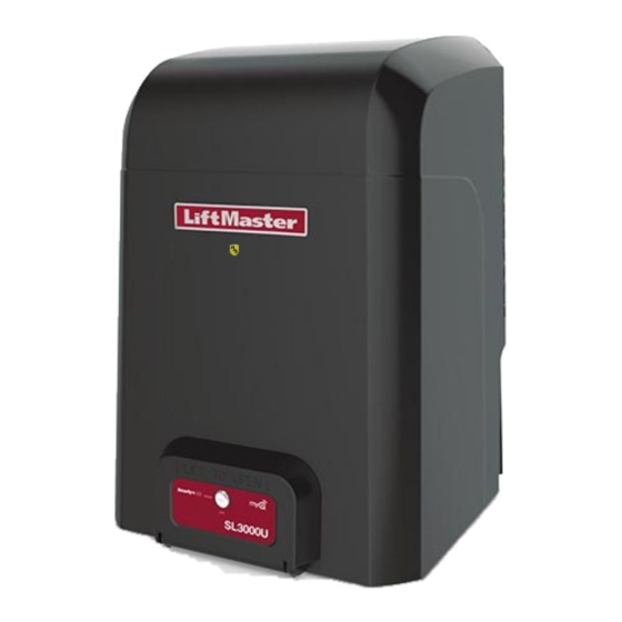
ELITE SERIES COMMERCIAL HIGH-TRAFFIC
AC SLIDE GATE OPERATOR
SL3000101U
1 HP Single Phase
SL3000501U
1/2 HP Single Phase
• THIS PRODUCT IS TO BE INSTALLED AND SERVICED BY A TRAINED GATE
SYSTEMS TECHNICIAN ONLY.
• This model is for use on vehicular passage gates ONLY and not intended for use
on pedestrian passage gates.
• This model is intended for use in Class I, II, III and IV vehicular slide gate
applications.
• Visit LiftMaster.com to locate a professional installing dealer in your area.
• This gate operator is compatible with MyQ
LiftMaster
845 Larch Avenue
Elmhurst, IL 60126-1196
INSTALLATION MANUAL
®
and Security+ 2.0
TM
accessories.
Advertisement
Table of Contents
Troubleshooting

Related Manuals for Chamberlain Elite SL3000


Summary of Contents for Chamberlain Elite SL3000
- Page 1 ELITE SERIES COMMERCIAL HIGH-TRAFFIC AC SLIDE GATE OPERATOR INSTALLATION MANUAL SL3000101U 1 HP Single Phase SL3000501U 1/2 HP Single Phase • THIS PRODUCT IS TO BE INSTALLED AND SERVICED BY A TRAINED GATE SYSTEMS TECHNICIAN ONLY. • This model is for use on vehicular passage gates ONLY and not intended for use on pedestrian passage gates.
-
Page 2: Table Of Contents
TABLE OF CONTENTS LOCKS ....................26 SAFETY SAFETY SYMBOL AND SIGNAL WORD REVIEW ........1 EXPANSION BOARD OVERVIEW USAGE CLASS ..................2 EXIT FAIL SWITCH ................27 UL325 ENTRAPMENT PROTECTION REQUIREMENTS ......2 AC FAIL SWITCH .................27 SAFETY INSTALLATION INFORMATION ..........3 ANTI TAIL SWITCH ................27 GATE CONSTRUCTION INFORMATION ..........4 QUICK CLOSE SWITCH ................27 INTRODUCTION... -
Page 3: Safety
SAFETY SAFETY SYMBOL AND SIGNAL WORD REVIEW When you see these Safety Symbols and Signal Words on the following pages, they will alert you to the possibility of Serious Injury or Death if you do not comply with the warnings that accompany them. The hazard may come from something mechanical or from electric shock. -
Page 4: Usage Class
SAFETY USAGE CLASS CLASS I – RESIDENTIAL VEHICULAR GATE OPERATOR A vehicular gate operator (or system) intended for use in garages or parking areas associated with a residence of one-to four single families. CLASS II – COMMERCIAL/GENERAL ACCESS VEHICULAR GATE OPERATOR A vehicular gate operator (or system) intended for use in a commercial location or building such as a multi-family housing unit (five or more single family units), hotel, garages, retail store, or other buildings... -
Page 5: Safety Installation Information
SAFETY SAFETY INSTALLATION INFORMATION Vehicular gate systems provide convenience and security. Gate The Stop and/or Reset (if provided separately) must be located in systems are comprised of many component parts. The gate the line-of-sight of the gate. Activation of the reset control shall not operator is only one component. -
Page 6: Gate Construction Information
SAFETY GATE CONSTRUCTION INFORMATION Vehicular gates should be installed in accordance with ASTM F2200: Standard Specification for Automated Vehicular Gate Construction. For a copy, contact ASTM directly at 610-832-9585 or www.astm.org. GENERAL REQUIREMENTS 3.1.2 All openings shall be designed, guarded, or screened from the bottom of the gate to the top of the gate or a minimum of 72 in. -
Page 7: Introduction
INTRODUCTION CARTON INVENTORY NOT SHOWN: Documentation Packet, Chain #41 - 30 feet, Eye Bolt Kit Key (2) Warning Signs (2) and Warranty Card Cover Operator LiftMaster Monitored Retro-Reflective Photoelectric Sensor TOOLS NEEDED • 1/2" wrench for cover screw 5/16" • 3/4" wrench for 1/2" concrete anchors •... -
Page 8: Operator Specifications
INTRODUCTION OPERATOR SPECIFICATIONS This model is intended for use in vehicular slide gate applications: Usage Classification Class I, II, III, & IV Model SL3000501U 1/2 HP: 120 Vac, 6 Amps (12 Amps including accessory outlets) Main AC Supply Model SL3000101U 1 HP: 120 Vac, 12 Amps (18 Amps including accessory outlets) Accessory Power 24 Vac, 500 mA max. -
Page 9: Site Preparation
INTRODUCTION SITE PREPARATION Check the national and local building codes BEFORE installation. SAFETY CONDUIT & CONCRETE PAD Entrapment protection devices are required to protect against any Conduit must be UL approved for low and high voltage. Consider entrapment or safety conditions encountered in your gate the operator placement BEFORE installing the pad or post. -
Page 10: Overview Of Typical Installation
INTRODUCTION OVERVIEW OF TYPICAL INSTALLATION IMPORTANT SAFETY INFORMATION: One or more external monitored entrapment protection sensors shall be located where the risk of entrapment or obstruction exists at either the opening or closing direction. Any gap larger than 2-1/4 inches between the gate and a fixed object such as a wall, pillar, column, or operator must be filled. -
Page 11: Installation
INSTALLATION • To AVOID damaging gas, power or other underground utility lines, • DO NOT touch the heater when switch is on, heater may be hot. contact underground utility locating companies BEFORE digging more than 18 inches (46 cm) deep. TYPES OF INSTALLATIONS STANDARD INSTALLATION REAR INSTALLATION... -
Page 12: Installation
INSTALLATION STEP 1 DETERMINE LOCATION FOR CONCRETE PAD AND OPERATOR Check the national and local building codes before installation. STANDARD INSTALLATION 1. The gate operator should be installed near the front roller of the gate. Lay out the concrete pad. 2. -
Page 13: Install The Operator
INSTALLATION STEP 2 INSTALL THE OPERATOR Attach the operator to the concrete pad with appropriate fasteners. The gate operator should be installed near the front roller of the gate or near the back of the gate (in the OPEN position). The space between the gate and the output sprocket must be a minimum of 4 inches. MOUNTING FOOTPRINT 10.4"... -
Page 14: Attach The Chain
INSTALLATION STEP 3 ATTACH THE CHAIN DO NOT run the operator until instructed. 1. Manually open the gate and line up the front bracket so the chain will be level with the idler pulley and parallel to the ground. Weld the front bracket in this position. -
Page 15: Install Entrapment Protection
INSTALLATION To prevent SERIOUS INJURY or DEATH from a moving gate: • Locate entrapment protection devices to protect in BOTH the open • ALL gate operator systems REQUIRE two independent entrapment and close gate cycles. protection systems for each entrapment zone. •... - Page 16 INSTALLATION STEP 4 continued... INSTALL ENTRAPMENT PROTECTION There are three options for wiring the entrapment protection devices depending on the specific device and how the device will function. Refer to the specific entrapment protection device manual for more information. These entrapment protection device inputs are for monitored devices, which include pulsed photoelectric sensors, resistive edge sensors, and pulsed edge sensors.
-
Page 17: Earth Ground Rod
INSTALLATION STEP 5 To Operator EARTH GROUND ROD Use the proper earth ground rod for your local area. The ground wire must be a single, whole piece of wire. Never splice two wires for the ground wire. If you should cut the ground wire too short, break it, or destroy its integrity, replace it with a single wire length. - Page 18 INSTALLATION STEP 6 continued... POWER WIRING 1. Make sure the AC power switch on the operator is OFF (the AC power switch will turn the incoming 120/240 Vac power ON or OFF). 2. Turn off the AC power from the main power source circuit breaker. 3.
-
Page 19: Dual Gates Only
INSTALLATION STEP 7 DUAL GATES ONLY There are two options for dual gate communication: wired or wireless. Follow the directions according to your application. Do not use wired and wireless communication simultaneously. WIRELESS DUAL GATES TO ACTIVATE THE WIRELESS FEATURE: 1. -
Page 20: Install The Cover
INSTALLATION STEP 7 continued... DUAL GATE WIRE TYPE (SHIELDED TWISTED PAIR CABLE) 22AWG up to 200 feet (61 m) 18AWG - 200-1000 feet (61-305 m) DUAL GATES ONLY Wire must be rated at 30 Volt minimum WIRED DUAL GATES Before digging, contact local underground utility locating companies. Use PVC conduit to prevent damage to cables. 1. -
Page 21: Adjust The Handing And Limits
INSTALLATION To reduce the risk of SEVERE INJURY or DEATH: • Without a properly installed safety reversal system, persons • NEVER use force adjustments to compensate for a binding or (particularly small children) could be SERIOUSLY INJURED or sticking gate. KILLED by a moving gate. -
Page 22: Obstruction Test
INSTALLATION STEP 9 (continued) ADJUST THE HANDING AND LIMITS ERASE THE HANDING 1. To erase the handing, press and hold the OPEN LEFT and OPEN RIGHT buttons simultaneously (5 seconds) until both the OPEN LEFT and OPEN RIGHT LEDs blink rapidly and the operator beeps. 2. -
Page 23: Operator Overview
OPERATOR OVERVIEW LIMIT SWITCHES Page 19 ANTENNA DUST GUARD CONTROL BOARD Pages 22-26 EXPANSION BOARD Pages 27-30 ACCESSORY POWER COVER OUTLET AC POWER SWITCH The AC Power switch on the MANUAL RELEASE HANDLE operator will turn the incoming Pull the manual release handle 120 Vac power ON or OFF. -
Page 24: Control Board Overview
CONTROL BOARD OVERVIEW CONTROL BOARD REFERENCE BIPART DELAY TIMER-TO-CLOSE Page 23 Page 23 DIAGNOSTIC DISPLAY FORCE DIAL Pages 23, 37-39 Page 24 TEST BUTTONS LEARN BUTTON Pages 24, 37 Pages 23, 32-33 BIPART DELAY CONTROL STATION TERMINALS Page 25 OPEN OPEN RIGHT LEFT... -
Page 25: Learn Button
CONTROL BOARD OVERVIEW LEARN BUTTON The LEARN button is used for programming (refer to Programming). DIAGNOSTIC DISPLAY The diagnostic display will show the operator type, firmware version, and codes. The operator type will display as “SL” followed by a “30” which indicates the operator type as SL3000U. -
Page 26: Force Dial
CONTROL BOARD OVERVIEW FORCE DIAL The force setting should be high enough that the gate will not reverse by itself nor cause nuisance interruptions, but low enough to prevent serious injury to a person. The force setting is the same for both the open and close gate directions. -
Page 27: Wire Accessories To Control Board
WIRE ACCESSORIES TO CONTROL BOARD THREE BUTTON CONTROL STATION TERMINALS FUNCTION WIRING EXAMPLE OPEN and COMM Opens a closed gate. Hard open (maintained switch overrides external safeties and resets alarm condition). If maintained, pauses Timer-to-Close at OPEN limit. Opens a closing gate and holds open an open gate (within line-of-sight). -
Page 28: Photoelectric Sensors And Edge Sensors
WIRE ACCESSORIES TO CONTROL BOARD PHOTOELECTRIC SENSORS AND EDGE SENSORS The EYES/EDGE terminals are used for connecting entrapment protection devices. At least one external monitored entrapment protection device is required prior to gate movement. Monitored entrapment protection devices should have been installed with the operator at the time of installation. Only ONE monitored device may be connected to each input. -
Page 29: Expansion Board Overview
EXPANSION BOARD OVERVIEW To AVOID damaging the circuit board, relays or accessories, DO NOT connect more than 42 Vdc (32 Vac) to the AUX relay contact terminal blocks. PLUG-IN LOOP DETECTOR INPUTS For Plug-In Loop Detectors (Model LOOPDETLM) POWER MAIN CONTROL BOARD CONNECTION Connected at the factory. -
Page 30: Auxiliary Relay 1 And 2
EXPANSION BOARD OVERVIEW AUXILIARY RELAY 1 AND 2 Normally Open (N.O.) and Normally Closed (N.C.) relay contacts to control external devices, for connection of Class 2, low voltage (42 Vdc [34 Vac] max 5 Amps) power sources only. Function of relay contact activation determined by switch settings. RELAY SETTING SWITCH SETTINGS AUX RELAY 1... -
Page 31: Wire Accessories To Expansion Board
WIRE ACCESSORIES TO EXPANSION BOARD PHOTOELECTRIC SENSORS AND EDGE SENSORS The EYES/EDGE terminals are used for connecting entrapment protection devices. At least one external monitored entrapment protection device is required prior to gate movement. Monitored entrapment protection devices should have been installed with the operator at the time of installation. Only ONE monitored device may be connected to each input. -
Page 32: Loops
WIRE ACCESSORIES TO EXPANSION BOARD LOOPS INPUTS FUNCTIONALITY WIRING EXAMPLE EXIT Loop wire connection for plug-in loop detector when loop is inside secured area near gate. • Open command - opens a closed gate • Soft open (maintained switch does not override external safeties and does not reset alarm condition) •... -
Page 33: Field Wiring
ADDITIONAL WIRING To protect against fire and electrocution: For continued protection against fire: • DISCONNECT power BEFORE installing or servicing operator. • Replace ONLY with fuse of same type and rating. FIELD WIRING CONTROL BOARD BIPART DELAY 3-BUTTON CONTROL – N.C. -
Page 34: Programming
PROGRAMMING REMOTE CONTROLS (NOT PROVIDED) A total of 50 Security+ 2.0 remote controls and 2 keyless entries (1 PIN for each keyless entry) can be programmed to the operator. When programming a third keyless entry to the operator, the first keyless entry will be erased to allow the third keyless entry to be programmed. When the operator’s memory is full it will exit the programming mode and the remote control will not be programmed. -
Page 35: Liftmaster Internet Gateway (Not Provided)
PROGRAMMING LIFTMASTER INTERNET GATEWAY (NOT PROVIDED) To program the operator to the LiftMaster Internet Gateway: Program using the learn button on the operator's control board: Program using the reset button on the operator: 1. Connect the ethernet cable to the LiftMaster Internet Gateway and 1. -
Page 36: Settings
SETTINGS GATE OPERATOR SETUP EXAMPLES The following are example setups for the gate operator. Your specific site requirements may be different. Always setup the operator system to the site requirements, including all necessary entrapment protection devices. One to four residential homes sharing a gated entrance/exit, allowing vehicle access trumps security concerns RESIDENTIAL: COMMERCIAL/GENERAL ACCESS: A residential community (more than four homes) having one or more gated entrances/exits, allowing... -
Page 37: Dual Gate Settings
SETTINGS DUAL GATE SETTINGS NOTE: We recommend that all accessories and board configurations are set on the primary operator. MAIN CONTROL BOARD FEATURE PRIMARY OPERATOR SECONDARY OPERATOR Timer-to-Close Set the TTC dial to desired setting Bi-Part Delay Switch Bi-Part Delay: ON (will open last and close first) Bi-Part Delay: OFF (will open first and close last) Tandem Mode: OFF Tandem Mode: OFF... -
Page 38: Maintenance
MAINTENANCE IMPORTANT SAFETY INFORMATION To reduce the risk of SEVERE INJURY or DEATH: • Test the gate operator monthly. The gate MUST reverse on contact • READ AND FOLLOW ALL INSTRUCTIONS. with a rigid object or reverse when an object activates the non- •... -
Page 39: Troubleshooting
TROUBLESHOOTING To protect against fire and electrocution: For continued protection against fire: • DISCONNECT power (AC or solar and battery) BEFORE installing or • Replace ONLY with fuse of same type and rating. servicing operator. DIAGNOSTIC CODES OPEN, CLOSE, & STOP BUTTONS TO VIEW THE CODES The codes will show on the diagnostic display. - Page 40 TROUBLESHOOTING DIAGNOSTIC CODES continued... Some codes are saved in the code history and some are not. If a code is not saved it will briefly appear on the display as it occurs, then disappear. Inherent Entrapment External Entrapment LiftMaster System Installed System Informational Protection...
- Page 41 TROUBLESHOOTING DIAGNOSTIC CODES continued... Some codes are saved in the code history and some are not. If a code is not saved it will briefly appear on the display as it occurs, then disappear. Inherent Entrapment External Entrapment LiftMaster System Installed System Informational Protection...
-
Page 42: Operator Alarm
TROUBLESHOOTING OPERATOR ALARM If a contact sensor detects an obstruction twice consecutively the alarm will sound (up to 5 minutes) and the operator will need to be reset. If a command is given after the initial 5 minutes the operator will beep. When the inherent force of the operator (RPM/current sensor) detects the following (twice consecutively) the alarm will sound (up to 5 minutes) and the operator will need to be reset:... -
Page 43: Troubleshooting Chart
TROUBLESHOOTING TROUBLESHOOTING CHART SYMPTOM POSSIBLE CAUSES SOLUTIONS Operator does not a) No power to control board a) Check AC power run and b) Open fuse b) Check fuses diagnostics display c) Defective control board c) Replace defective control board not on. Control board a) Reset switch is stuck a) Check reset switch... - Page 44 TROUBLESHOOTING TROUBLESHOOTING CHART continued... SYMPTOM POSSIBLE CAUSES SOLUTIONS Shadow loop does a) Vehicle detector setup incorrectly a) Review Shadow loop detector settings. Adjust settings as needed. not keep gate at b) Defective vehicle loop detector b) Replace defective Shadow loop detector. open limit.
-
Page 45: Accessories
ACCESSORIES INTERNET PROTOCOL ACCESS CONTROL UNIVERSAL REMOTE CONTROLS SECURITY+ 2.0 LEARNING REMOTE CONTROLS IPAC 813LM 894LT LIFTMASTER INTERNET GATEWAY 811LM 828LM 892LT LIFTMASTER DOOR AND GATE MONITOR Model 829LM PLUG IN LOOP DETECTOR LOOPDETLM HEATER KIT ACCESSORY AC/DC LIFTMASTER ELITE SERIES 3 BUTTON CONTROL STATION HTRNB MAGLOCK PACKAGE... -
Page 46: Repair Parts
REPAIR PARTS NOT SHOWN #41 Chain (10 feet) 19-41240D #40 Chain (10 feet) 19-40240D #41 Chain (Nickel Plated) 19-41240D-NP Cover #41 Master Link 19-50307 K77-37708 #40 Master Link 19-50310 Plastic Standoffs for main control board (10 per bag) K77-37683 Wire Harnesses (main board to power board, main board to ground, main board to K77-37693 transformer, and power board to transformer) Wire Harness (main board to expansion board) -
Page 47: Warranty
WARRANTY 7 YEAR RESIDENTIAL / 5 YEAR COMMERCIAL LIMITED WARRANTY LiftMaster (“Seller”) warrants to the first purchaser of this product, for the structure in which this product is originally installed, that it is free from defect in materials and/or workmanship for a period of 7 year residential/ 5 year commercial from the date of purchase [and that the SL3000U is free from defect in materials and/or workmanship for a period of 7 year residential/ 5 year commercial from the date of purchase]. - Page 48 845 Larch Avenue Elmhurst, Illinois 60126-1196 LiftMaster.com 01-37920 © 2015, LiftMaster – All Rights Reserved...
Need help?
Do you have a question about the Elite SL3000 and is the answer not in the manual?
Questions and answers