
Subscribe to Our Youtube Channel
Related Manuals for Deprag MINIMAT 347-210-31UL


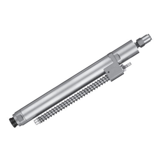
Summary of Contents for Deprag MINIMAT 347-210-31UL
- Page 1 012754en Operating Instruction Booklet Stationary Screwdriver Spindle 347-210-31UL 397079 A 347-310-31UL 397079 B 347-510-31UL 397079 C 347-610-31UL 397079 D 347-910-31UL 397079 E MINIMAT...
-
Page 2: Table Of Contents
We kindly ask that you read these operating instructions carefully so that you will be able to use this tool safely and for many years to come. If you need additional information, please contact your DEPRAG Representative, one of our international support offices or us direct at DEPRAG. -
Page 3: Safety Tips
Safety Tips 1.1. General Safety Tips Before operating tool make sure to carefully read and observe this operating instruction. Generally, the operator of the equipment and/or machinery is responsible for the equipment’s perfect condition and operation, while observing all necessary safety regulations. -
Page 4: General Safety Tips For Pneumatic Stationary Screwdriver Spindles
1.2. General Safety Tips for Pneumatic Stationary Screwdriver Spindles • Disconnect the tool from the air supply, when changing bits or when re-adjusting clutch. • Do not wear wide clothing or jewelry, for they can be seized by movable parts. Wear a hairnet if operator has long hair. •... -
Page 5: Operator Obligation
1.4. Operator Obligation Personnel, who is engaged in the operation of the equipment, must always be committed to • observe the basic safety and accident preventing regulations, • read and observe the safety and warning notifications of this operating instruction booklet. 1.5. -
Page 6: Symbol Description
1.6. Symbol Description Read and observe the Operating Instruction Booklet, prior to and during operation of tool. DANGER Reference to an immediate danger to a person. May lead to serious injuries or even death if unobserved! Properly recycle environmentally damaging grease, cooling agents or detergents. - Page 7 Maintenance and repair on hydraulic and pneumatic equipment may only be performed by specially trained personnel! Disconnect equipment from air supply, prior to repair of pneumatic or hydraulic equipment. Provide regular preventive maintenance on hoses and airlines. Exchange hose lines, even if there is no visible damage! (Observe corresponding requirements of the manufacturer!) After repair and maintenance, check the following items: •...
-
Page 8: Observe Environmental Regulations
1.7. Observe Environmental Regulations When working on or with the equipment, it is imperative to observe all requirements in regards to waste-disposal and proper recycling. Especially during installation, repair or maintenance, water damaging agents such as • lubricating grease and oil •... -
Page 9: Installation
The hose length should not exceed 2 meters. • All DEPRAG Screwdrivers may be operated either with or without lubricated air (see paragraph: Maintenance and Upkeep). Best results are achieved, when machine is lubricated with 1 – 2 drops of oil per 1m... - Page 10 OUR RECOMMENDATION: The preferred lubricating method for the screwdriver spindles mounted in fixtures, brackets, machines, etc., each in connection with a controller, is method b) with Point-of-Use Oiler. • Check pressure at directly on the machine. The Regulator needs to be adjusted to an airflow between 5.0 (71 PSI) and 6.3 bar (90 PSI).
-
Page 11: Operation
Adjust clutch to the required torque value. If necessary, exchange clutch spring. The necessary torque adjustment can be tested, using a DEPRAG Torque Wrench or Measuring Platform (see DEPRAG catalogs D3020 and D3022 ). This equipment can also be used to re-adjust the torque of the Screwdriver Spindle. -
Page 12: Range And Exchange Of Clutch Spring
(otherwise it will result in reduced performance). 4.1. Range and Exchange of Clutch Spring The torque range of the DEPRAG Screwdriver is adjustable. Please see a listing for the torque ranges of the color-coded springs below. Torque Range of the individual clutch spring: -∅... - Page 13 NOTICE The claw of the clutch must engage with the claw of the spin- dle! An external torque adjustment of the clutch is again possible (see chap- ter Torque Adjustment ). half-round bore clutch spring claw of the clutch adjustment nut Picture: Exchange of clutch spring Make sure to screw adjustment (adjusting) nut onto clutch shaft until one line of the thread is visible.
-
Page 14: Torque Adjustment
4.2. Torque Adjustment For an external torque adjustment use the following steps: Disconnect the screwdriver from the air supply. Insert the supplied hand screwdriver 326240 through one of the slots on the motor housing into the half-round bore of the lock ring (if necessary, turn bit by hand). -
Page 15: Connection-Possibilities Of The Function Control
4.3. Connection-Possibilities of the Function Control Use as air pressure outlet during screw-assembly: • to control driver start and stop, as well as shut-off control of clutch; • as cycle counter of the complete process; each in connection with a PE-Switch or similar This function control is under pressure of appx. -
Page 16: Change Of Bits
4.4. Change of bits CAUTION Always disconnect the screwdriver from air supply prior to changing bits, to avoid the unintentional start of the screwdriver, which may result in injuries. Before exchange of bits, the clutch bearing has to be in place. -
Page 17: Disassembly - Assembly
After repair or maintenance, verify that equipment runs to specification! Principally, use only DEPRAG original spare parts. Otherwise, a reduction in equipment power-output and an increased maintenance-requirement occurs. If NON-DEPRAG parts are installed, DEPRAG is justified to void any existing warranty and liability obligations. ATTENTION... - Page 18 Pull off the flange 3384556 with the complete guide bolt 401115 C from the valve housing 401130. Take out the valve set 401168 D. 10. Unscrew the valve housing 401130 (AF 10, right-hand thread) from the motor housing 3988561. 11. Remove the intermediate ring 4011201 and push the motor with the gea- ring out of the motor housing towards air inlet side.
-
Page 19: Special Repair Tools (Optional Equipment)
Assembly: Use the DEPRAG Grease 807293 (100-g tube) to grease the ball bearing, needle bearing and gearing parts prior to reassembly. a. Clean rotor. b. Press the ball bearings into the two bearing covers. c. Press the shaft-side bearing cover with the ball bearing on the rotor. -
Page 20: Correct Assembly Of Shut-Off Function On Clutch
5.2. Correct Assembly of Shut-Off Function on Clutch ATTENTION If the stop-pin is installed incorrectly, the clutch will NOT shut -off. In between the two curves, the taper of the stop pin has to point towards the outside (as illustrated in the pictures below). Curves Taper on Stop Pin... -
Page 21: Spare Part Drawings
5.3. Spare Part Drawings... - Page 26 --------------------------------------------------------------------------------------------------------------------------------------------------------- ---------------------------------------------------------------------------------------------------------------------------------------------------------...
- Page 27 ----------------------------------------------------------------------------------------------------------------------------------------------------------- ----------------------------------------------------------------------------------------------------------------------------------------------------------- -----------------------------------------------------------------------------------------------------------------------------------------------------------...
- Page 28 ------------------------------------------------------------------------------------------------------------------------------------------------ ------------------------------------------------------------------------------------------------------------------------------------------------ ------------------------------------------------------------------------------------------------------------------------------------------------...
-
Page 29: Spare Parts Drawings For Accessories
5.4. Spare Parts Drawings for Accessories ------------------------------------------------------------------------------------------------------------------------------------------------... -
Page 30: Installation Tips For Screwdriver Spindle
5.5. Installation Tips for Screwdriver Spindle... -
Page 31: Maintenance And Upkeep
6 months (single shift). • Exchange broken or worn inserting tools immediately, for they can cause injury to the Operator. • If tool malfunctions, we recommend to send the machine to DEPRAG. 6.1. Wear Parts UANTITY... -
Page 32: Trouble Shooting
Maintain air pressure of 90 PSI shut-off or for required torque ratchets value Valve Pin is too long Check length of valve pin, either shorten or replace valve pin (picture: Actual Size of Valve Pin) If necessary, please send tool to DEPRAG for service. -
Page 33: Delivery Capacity
Picture: Actual Size of Valve Pin WARNING When connecting to compressed air supply valve pin may be catapulted out which may cause serious injuries. When verifying the actual size of the valve pin, make sure NOT to hold the screwdriver directed towards yourself or any other person. - Page 34 Finder and bit are not included in the delivery capacity of the spring sleeve. You will find suitable inserting tools • in our brochure D 3320 E or • on the internet as follows: → Screwdriving www.deprag.com Technology→ Selection program: Inserting tools...
-
Page 35: Storage
Mount the exhaust connection 386924 G (in the screwdriver axis) resp. 386924 H (right-angled to the screwdriver axis) as follows: Disconnect screwdriver from air supply. Clamp screwdriver spindle always with chucking jaws into a vice, utilizing the flats of the motor housing (otherwise motor- and gearing parts may be damaged). -
Page 36: Technical Data
11 Technical Data Manufacturer DEPRAG SCHULZ GMBH u. CO. Address Kurfürstenring 12 - 18 P.O. Box 1352 D-92224 Amberg D-92203 Amberg Phone 09621/371-0 09621/371-120 Technical Data: 347-210- 347-310- 347-510- 347-610- 347-910- 31UL 31UL 31UL 31UL 31UL 397079 397079 397079 397079 397079 Part No. -
Page 37: Declaration Of Manufacturer
13 Declaration of Manufacturer EC-Declaration of Manufacturer in accordance with the CE-Machine-Guideline 98/37/EC, appendix II B DEPRAG SCHULZ GMBH u. CO. Kurfürstenring 12 – 18 Postfach 1352 D-92204 Amberg D-92203 Amberg declares, that the construction of the stationary screwdriver spindle... -
Page 38: Service Locations And Authorized Partners
D-92203 Amberg F ax: +98 (0) 21 / 66009451 DEPRAG China Tel.: +49 (0) 9621 / 3 71-0 e-mail: naccarson_airtools@yahoo.c om DEPRAG Assembly Technologies Fax: +49 (0) 9621 / 3 71-1 20 (Suzhou) Co., Ltd. IRELAND Internet: http://www.deprag.com No. 111, Hong Ye Rd, Blk. 4 Unit D e-mail: info@deprag.de... - Page 39 Tel.: + 1 / 972 / 221 – 8731 e-mail: asiaingenieur@gmail.com ISANDO Fax: + 1 / 972 / 221 – 8163 Internet: www.geocities.com/farsberg 1600 Toll Free: (800) 4 DEPRAG Republic of South Africa Internet: http://www.deprag.com MOROCCO Tel.: +27 11 392 2367 e-mail: deprag@depragusa.com...
- Page 40 DEPRAG SCHULZ GMBH u. CO. Postfach 1352, D-92203 Amberg Kurfürstenring 12-18, D-92224 Amberg (09621) 371-0 (09621) 371-120 Internet: http://www.deprag.com e-mail: info@deprag.de...
Need help?
Do you have a question about the MINIMAT 347-210-31UL and is the answer not in the manual?
Questions and answers