Table of Contents
Advertisement
Quick Links
Advertisement
Table of Contents

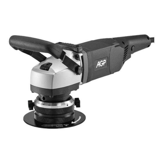
Summary of Contents for AGP EB12
- Page 1 EB12 Instruction Manual...
- Page 2 1800 W Power Input Voltage See machine nameplate No Load Speeds (n 2300-6500 min Speed Wheel Settings 1: 2300 / 2: 2600 / 3: 3700 / 4: 4800 / 5: 5800 / 6: 6500 min Std. Bevel Angle 45° (optional 37.5°, 30°) Max.
-
Page 3: General Safety Instructions
GENERAL SAFETY INSTRUCTIONS WARNING! Read all safety warnings and all instructions. Failure to follow the warnings and instructions may result in electric shock, fire and/or serious injury. Save all warnings and instructions for future reference. The term “power tool” in the warnings refers to your mains operated (corded) power tool or battery-operated (cordless) power tool. - Page 4 4) POWER TOOL USE AND CARE Do not force the power tool. Use the correct power tool for your application. The correct power tool will do the job better and safer at the rate for which it was designed. Do not use the power tool if the switch does not turn it on and off. Any power tool that cannot be controlled with the switch is dangerous and must be repaired.
-
Page 5: Specific Safety Rules
SPECIFIC SAFETY RULES Never operate the tool in an area with flammable solids, liquids, or gases. Sparks from the commutator/ carbon brushes could cause a fire or explosion. Warning:Risk of injury from high-temperature chips! High-temperature chips are expelled at high speed. Never touch the tool holder and keep all vulnerable body parts clear while the machine is running. -
Page 6: Extension Cable
EXTENSION CABLE If an extension cable is required, it must have a sufficient cross-section so as to prevent an excessive drop in voltage or overheating. An excessive drop in voltage reduces the output and can lead to failure of the motor. The following table shows you the correct cable diameter as a function of the cable length for this machine. - Page 7 support deck, slowly adjust the support deck until the ruler just touches the carbide insert. This is the zero point. Once the zero point is found, loosen the small set screw and turn the dial ring to indicate zero on the scale.
-
Page 8: Speed Control Wheel
To lock the switch on, press the lock pin next to the switch. To switch off Squeeze and release the trigger switch to unlock the switch and switch off. After the machine has been switched off, the arbor will still rotate for a time. Take care that parts of your body do not come into contact with the rotating parts or set the machine down while it is still rotating! Variable speed wheel SPEED CONTROL WHEEL... - Page 9 2. Lubrication Every 100 hours of operation, have the gearbox grease replaced by a qualified service technician. 3.Replace the impeller when worn When the impeller becomes worn the workpiece surfaces will be machined unevenly. Replace when worn as follows: Using the supplied hook spanner wrench, engage one of the holes in the tool holder to immobilize it. Using an appropriate sized wrench loosen the nut securing the impeller and remove.
-
Page 10: Exploded View
EXPLODED VIEW... -
Page 11: Parts List
PARTS LIST Parts Name Q'TY Parts Name Q'TY POWER SUPPLY CABLE (VDE-1.5x2Cx3M-H05VVF) INTERNAL CIRCLIP (R-47) CORD ARMOR EXTERNAL CIRCLIP (S-20) CABLE CLIP BALL BEARING (6204) PANHEAD TAPPING SCREW (M4x14) PARALLEL KEY (5x5x12) SWITCH (110V/220V) SPINDLE (M14xP2.0-122.8MM) PANHEAD TAPPING SCREW (M4x30) INNER SUPPORT BARREL PANHEAD TAPPING SCREW (M4x16) SOCKET CAP SCREW (M5x25xP0.8) - Page 12 WIRING...


Need help?
Do you have a question about the EB12 and is the answer not in the manual?
Questions and answers