
Related Manuals for BIRD 4421A


Summary of Contents for BIRD 4421A
- Page 1 Power Meter 4421A Operation Manual © Copyright 2022 by Bird Technologies, Inc. Instruction Book Part Number 920-4421A Rev. D...
-
Page 3: Safety Precautions
Safety Precautions Safety Precautions The following are general safety precautions that are not necessarily related to any specific part or procedure, and do not necessarily appear elsewhere in this publication. These precautions must be thoroughly understood and apply to all phases of operation and maintenance. -
Page 4: Safety Symbols
See page 16 and 18 WARNING To avoid personal injury, disconnect the power cord from the AC line before performing any maintenance. See page 29 WARNING The Bird 4421A contains no user-serviceable parts. Do not open the cover. See page 29... -
Page 5: Caution Statements
Do not exceed the RF Power or RF frequency specifications of the RF Power Sensor. See page 16 CAUTION Do not store the 4421A outside the following temperature ranges -10° to 50°C, ≤ 1 month -10° to 35°C, ≤ 6 months -10° to 25°C, > 6 months Storage outside these temperature ranges may degrade battery capacity. -
Page 6: Safety Statements
4421A Power Meter Safety Statements USAGE ANY USE OF THIS INSTRUMENT IN A MANNER NOT SPECIFIED BY THE MANUFACTURER MAY IMPAIR THE INSTRUMENT’S SAFETY PROTECTION. EL USO DE ESTE INSTRUMENTO DE MANERA NO ESPECIFICADA POR EL FABRICANTE, PUEDE ANULAR LA PROTECCIÓN DE SEGURIDAD DEL INSTRUMENTO. - Page 7 Safety Precautions SERVICE SERVICING INSTRUCTIONS ARE FOR USE BY SERVICE - TRAINED PERSONNEL ONLY. TO AVOID DANGEROUS ELECTRIC SHOCK, DO NOT PERFORM ANY SERVICING UNLESS QUALIFIED TO DO SO. SERVICIO LAS INSTRUCCIONES DE SERVICIO SON PARA USO EXCLUSIVO DEL PERSONAL DE SERVICIO CAPACITADO. PARA EVITAR EL PELIGRO DE DESCARGAS ELÉCTRICAS, NO REALICE NINGÚN SERVICIO A MENOS QUE ESTÉ...
-
Page 8: About This Manual
Identifies steps required to power on, use, and power off the Power Meter. Troubleshooting — Provides limited troubleshooting instructions for commonly encountered problems. Maintenance — Lists routine maintenance tasks as well as storage and shipping instructions. Specifications — Provides the specifications for the Bird RF Power Meter. -
Page 9: Table Of Contents
4421A SCPI Command Syntax ........ - Page 10 Attach 4421A to Rack Mount ........46...
-
Page 11: Chapter 1 Introduction
The Bird 4421A Power Meter is used with Bird power sensors to measure RF power. General Description The 4421A Power Meter is designed to be used with the Bird Power Sensors as shown in . The 4421A is equipped with a touchscreen interface. There... -
Page 12: 4421A Options
Note: Licenses may be purchased to implement increased capabilities of higher level models. Optional Rack Mount Kit A rack mounting kit (Bird Part Number 4421A-RM1) is available for the 4421A, Appendix 1, Optional Rack Mount on page 41... -
Page 13: Controls And Indicators
Introduction Controls and Indicators Figure 2 Models 4421A-10-00-0, 4421A-20-00-0, 4421A-10-11-0, 4421A-20-11-0 Figure 3 Model 4421A-12-11-1 Item Indicator Description Displays Power Sensor information and acts as the Display/Touch Screen user interface. Used to apply and remove power from the unit. Illuminated ring indicates power is applied to the unit. - Page 14 Ethernet connector provides access to the device’s Ethernet Connector web UI and firmware update capability. The serial port allows computer interface capability with the 4421A using either the "4421A SCPI Commands" on page 19 the"Legacy RS-232 Commands" on page 24...
-
Page 15: Display Features
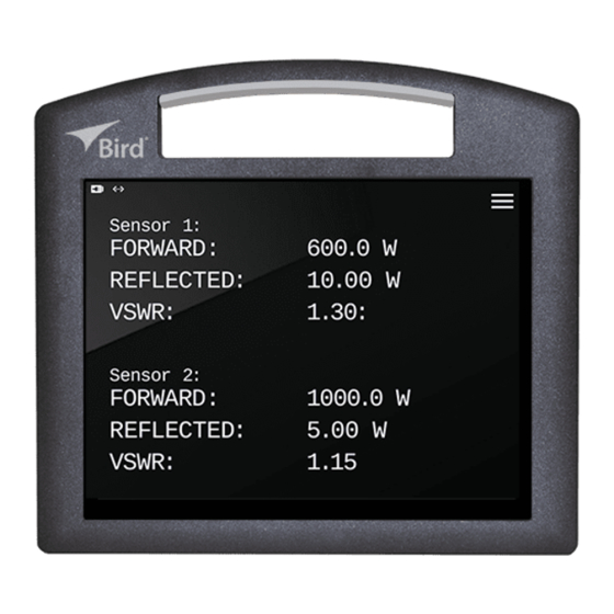
Introduction Display Features The 4421A display is capable of displaying the measurement information from one or two sensors simultaneously (model dependent), see . The Figure 4 display may be configured to display the following measurements from a sensor: Forward Power ... -
Page 16: Display Controls And Indicators
Display Controls and Indicators The display is used for presenting information and controlling the behavior of the 4421A. The controls are those items displayed on the screen, that, when tapped cause a change in the 4421A’s behavior. Controls can be identified by their color, on screen controls are yellow. - Page 17 The sensor readings for Forward and Reflected power may be displayed in milliwatts, Watts, Kilowatts, or dBm. Forward and In overrange situations, the 4421A will display the Reflected Power word “RANGE” in place of the actual power reading. When Reflected power measurement is dBm, -inf dBm means the reflected power was 0 W (exactly).
- Page 18 4421A Power Meter The graph’s time scale auto expands as data accumulates with the following scales: • 60, 120, 240, 480 seconds • 15, 30, 60, 120, 240 minutes Time Scale • 8, 16, 24 hours Data accumulation stops at 24 hours.
-
Page 19: Settings Menu
Introduction Settings Menu The setting menu is used to select what information will appear on the 4421A’s display as well as configuration of the LAN and Serial Ports. describes Figure 6 the options available via the setting menu. Figure 6... -
Page 20: Graph Settings Menu
4421A Power Meter Displays the units Model Number, Serial Number, and About Firmware ID. Compliance and software licensing information may also be viewed from the About menu. Graph Settings Menu The Graph Settings menu is accessed by tapping the power scale on the graph. - Page 21 Introduction Numeric entry for specifying the number of samples Count, used for the moving average. Applied when Average On Graphing Mode is selected. When tapped, applies all menu changes and closes the Apply dialog box. When tapped, cancels all menu changes and closes the Cancel dialog box.
-
Page 22: Remote Interfaces
IP Address Settings Display The LAN option on the menu is used to access the IP Address configuration menu. This menu displays the current IP Addresses for the 4421A. The 4421A has a dual IP Address configuration. Fixed IP Address: 192.168.44.21 (this address cannot be changed) ... -
Page 23: Rs-232 Serial Interface
Introduction RS-232 Serial Interface The Bird 4421A’s RS-232 interface feature is provided to allow remote measurement control. The RS-232 is only operational on models with the appropriate license installed and activated, see "4421A Options" on page 2 The RS-232 interface uses a standard 9-pin connector. The commands available... -
Page 24: Rs-232 Cable Connector
RS-232 Cable Connector The interface uses a standard 9 pin connector. Pin assignments are listed in . The 4421A serial port is wired as a “null modem” with all the Table 3 handshaking signals looped back. The only active pins are 2 and 3, referenced to ground on pin 5. -
Page 25: Chapter 2 Setup
4. Turn on the 4421A and make sure the charge icon is displayed. 5. Leave the 4421A on and connected to AC until the first full charge has been reached and the plug icon is displayed. Note: This will ensure that the battery remaining % is accurate... -
Page 26: Setup
4421A Power Meter Setup Setup consists of ensuring the 4421A has a power source, internal batteries or AC power source, and attaching a Bird Power Sensor. Use the 4421A in a dry, dust-free environment. AC power source, if used, is 100 - 240 V @ 50/60 Hz, 1W. -
Page 27: Vesa Mount
1. Position the VESA mount on the rear of the 4421A enclosure. 2. Insert the recommended screws into the washers, then drive screws into the indented holes on the rear of the 4421A. The screw will break through a thin plastic barrier. -
Page 28: Chapter 3 Operating Instructions
RF transmission line. See "Setup" on page 16 additional information regarding setup of the 4421A. 1. Press Power button on the Bird 4421A power meter side panel. 2. The 4421A takes approximately 30 seconds to complete the boot-up sequence. -
Page 29: Chapter 4 4421A Scpi Commands
Chapter 4 4421A SCPI Commands 4421A Standard Commands for Programmable Instruments (SCPI) commands are used to control the 4421A over Ethernet or RS-232 interface. 4421A SCPI Command Syntax A command is made up of one or more keywords. Consecutive keywords are separated with colons (:). - Page 30 4421A Power Meter Lower- case lettering indicates the portion of the command that is optional; it can either be included with the upper- case :IDENtity portion of the command or omitted. This is the flexible format principle called Either :IDEN, :IDENtity, or :IDENTITY forgiving listening.
-
Page 31: 4421A Scpi Commands
4421A SCPI Commands 4421A SCPI Commands Common Commands *IDN? Description — Identification Query Parameter Type — <arbitrary_ascii> Parameter Minimum — Parameter Maximum — Parameter Default — Parameter Values — Parameter Units — Returns device identification in the following format: Response —... -
Page 32: System Commands
4421A Power Meter MEASure[:SCALar][:POWer]:REFLected:AVERage? [1 or 2] Description — initiate, and retrieve a reflected average power measurement. Parameter Type — <NR1> Parameter Minimum — Parameter Maximum — Parameter Default — Parameter Values — Parameter Units — Response — Returns the Reflected average power in W from the specified sensor channel. - Page 33 4421A SCPI Commands SYSTem:IDENtity:SN? Description — Get the device serial number. Parameter Type — <arbitrary_ascii> Parameter Minimum — Parameter Maximum — Parameter Default — Parameter Values — Parameter Units — Response — Returns the serial number as given in the response.
-
Page 34: Chapter 5 Legacy Rs-232 Commands
A group of device-dependent commands can be sent as a single string as long as like command categories are not repeated. For example: “FCT1ENT”. This string sets up the 4421A to read forward carrier wave, make one reading on “T1”, and triggers (ENT) a measurement. -
Page 35: General Bus Commands
Sends a reading to the controller INiTialize (INT) Function Resets the Bird 4421 and returns it to the factory defaults. Remarks If INT is linked with any other command within a string, it must be separated from that command by a space. -
Page 36: Device Dependent Commands
Selects forward or reflected RF power measurement mode. Remarks Measurement results are returned in Watts. Range (RYY) Function Sets the 4421A to auto range, legacy command to provide compatibility with previous 4421 units. Remarks Auto is the only range setting available. Terminators (YT) Function Selects the characters that follow the end of a data string. - Page 37 “O” indicates overflow; the value sent is “199.9”. “N” indicates normal; the value sent is a normal on- scale reading. “4421” indicates the Bird model number. Table 9 Prefix Examples Data String Description NFC.0.123W(CR)(LF) Normal (N) forward carrier wave (FC), prefixes on OFC 199.9W(CR)(LF)
-
Page 38: Chapter 6 Troubleshooting
4421A. Is the sensor cable defective? Replace sensor cable. Connect the AC power cord while the 4421A is running and wait for the battery indicator to display the plug icon . Battery remaining % Battery fuel gauge has lost sync does not agree with with the battery. -
Page 39: Chapter 7 Maintenance
Check the connectors and cables for damage. Storing the 4421A If the 4421A is stored, charge the batteries every 6 months. See "Charge the Battery" on page 15 AC Power Cable Only replace the A/C input power supply cable with a cable of equivalent rating, and capable of supporting the 4421A power specifications, see "Specifications"... -
Page 40: Web User Interface
PC connected to the 4421A. 4421A’s Fixed IP Address: 192.168.44.21 To access the WEB UI the PC connected to the 4421A must be on the same subnet as the 4421A. See "Configuring PC Network Settings to 4421A Subnet"... -
Page 41: Configure Static Ip Address
Maintenance Configure Static IP Address Note: NetMask and Gateway are optional. 1. Tap the menu ICON. 2. Tap the menu option, and select LAN. 3. Tap the Configure button. See Figure 13 Figure 13 IP Address Display 4. Select the manual radio button. See Figure 14 Figure 14 IP Address Configuration Screens... -
Page 42: Configure Dhcp
4421A Power Meter 10. Tap the Gateway text area, and enter the Gateway IP Address. 11. Tap 12. Tap Apply to save and exit. 13. Tap the menu ICON. 14. Tap the menu option, and select LAN. 15. Verify the IP Address was saved. -
Page 43: Touchscreen Calibration
Note: A popup confirmation message will be displayed. 7. Click OK on the confirmation message to complete reset. 8. Wait for “Successfully Reset ….” message to be displayed. 9. Press power button on the side of the 4421A to remove power. - Page 44 12. Tap each calibration point as they are displayed, beginning in the upper left of the screen. Note: After tapping each calibration point in each corner of the display the 4421A will complete power up and display the RF measurement screen.
-
Page 45: Configuring Pc Network Settings To 4421A Subnet
Maintenance Configuring PC Network Settings to 4421A Subnet Use this procedure to configure a PC to communicate via an Ethernet connection with the 4421A. Note: These instructions apply to a Windows 7/10 PC. 1. Select Start->Control Panel->Network and Sharing Center on the PC. -
Page 46: Firmware Update
4421A Power Meter Firmware Update Obtain Firmware 1. Firmware files for the 4421A may be downloaded from the product page on Birdrf.com. 2. Download the Firmware File (.zip file). 3. Save the license file on the PC you will use to install the license on the 4421A. - Page 47 Maintenance Figure 22 Choose Firmware File 8. Click the Load New Firmware button. Figure 23 Load Firmware 9. Wait for “Firmware flashing completed successfully” message 10. Click Restart button. 11. Once restart is complete, verify the firmware update is complete.
-
Page 48: Storage And Shipment
Storage outside these temperature ranges may degrade battery capacity. 1. Cover Bird 4421A Power Meter before storing to keep out dust and dirt. 2. Store in a dry, dust-free environment where the ambient temperature will remain between those specified in for the "Specifications"... -
Page 49: Chapter 8 Specifications
Chapter 8 Specifications Bird 4421A Power Meter Specifications Note: The 4421A Power Meter is intended for indoor use only. Compatible Bird Power Model Dependent: Sensors All Models: 4021, 4022, 4023, 4024, 4025, 4027, 4028 4421A-12-11-1: 7027-series, 7037-series Sensor Detection Automatic Sensor detection Two sensors may be connected and measurements displayed simultaneously. - Page 50 4421A Power Meter AC/DC Power Supply Input Voltage 100 - 240 V @ 50/60 Hz, 1 30 W. Main Supply Voltage ± 10 % Fluctuations Over-voltage Category Category II Pollution Degree Certifications MIL28800 CLASS 4; SGS Physical Characteristics H x W x D Dimensions, 9 11/16 in.
-
Page 51: Appendix 1 Optional Rack Mount
4421A, making it easy to find the perfect viewing angle. The 4421A can be mounted anywhere from 1/2‘’ up to 9-1/2” depth in a rack in increments of 1/4". All Rack Mount assembly hardware and rack mounting hardware is included. -
Page 52: Rack Mount Kit Assembly
4421A Rack Mounting Kit Rack Mount Kit Assembly This section provides unpacking, inspection, and assembly instructions for the 4421A Rack Mount Kit. Rack Mount Kit Contents The Rack mount kit includes the brackets and sub-assembly shown in Figure 25 and attaching hardware listed below. - Page 53 Figure 26 Attach VESA Bracket 3. Insert the screws into the washers, then drive screws into the indented holes on the rear of the 4421A. The screw will break through a thin plastic barrier. CAUTION Do not over tighten the screws. Over tightening will strip the plastic and the screw will not hold the 4421A to the VESA bracket.
- Page 54 Depth Bracket Attachment Note: The holes in the Depth Brackets determine how far into the rack the 4421A will be when mounted to the Rack Mount Assembly. 1. Secure one of the Depth Brackets to the Horizontal Bracket using two 10-32 Flat Head Screws.
- Page 55 Optional Rack Mount Rack Installation Attach the Assembly to the Rack using six (6) of the appropriate Rack Mounting Hardware. Figure 29 Rack Instalation The Rack Hardware Kit provides various screws and nuts for the four most common types of racks. ...
-
Page 56: Attach 4421A To Rack Mount
The VESA bracket attached to the 4421A allows the unit to easily connect and disconnect with the rack mount. 1. Position the slots on the 4421A VESA Mount over the tabs on the top of the Pan/Tilt Assembly. Figure 30 Attach 4421A to Rack Mount 2. -
Page 57: Limited Warranty
Limited Warranty All products manufactured by Seller are warranted to be free from defects in material and workmanship for a period of one (1) year, unless otherwise specified, from date of shipment and to conform to applicable specifications, drawings, blueprints and/or samples. Seller’s sole obligation under these warranties shall be to issue credit, repair or replace any item or part thereof which is proved to be other than as warranted;...
Need help?
Do you have a question about the 4421A and is the answer not in the manual?
Questions and answers