
Related Manuals for KROHNE OPTISWITCH 3000 Series


Summary of Contents for KROHNE OPTISWITCH 3000 Series
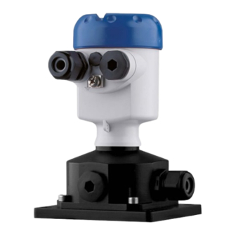
- Page 1 External housing Supplementary instructions Vibrating Level Switch OPTISWITCH series 3000...
-
Page 2: Table Of Contents
Contents Contents About this document ....................... 3 Function ........................... 3 Target group ........................3 Symbols used........................3 For your safety ......................... 4 Authorised personnel ....................... 4 Appropriate use ........................ 4 Safety instructions for Ex areas ..................4 Product description ......................... 5 3.1 Configuration ........................ -
Page 3: About This Document
1 About this document About this document Function This supplementary instructions manual is valid in conjunction with the operating instructions of the instrument. It gives you all necessary information for a quick setup and safe operation of the instrument with accessory. -
Page 4: For Your Safety
2 For your safety For your safety Authorised personnel All operations described in this operating instructions manual must be carried out only by trained qualified personnel authorised by the plant operator. During work on and with the device, the required personal protective equipment must always be worn. Appropriate use An external housing is part of a sensor. Safety instructions for Ex areas Take note of the Ex specific safety instructions for Ex applications. -
Page 5: Product Description
3 Product description Product description 3.1 Configuration Scope of delivery The scope of delivery encompasses: • Level sensor with external housing • Documentation – A device operating instructions manual – To this supplementary operating instructions – Ex specific safety instructions (with Ex versions), if necessary further certificates The instrument version "External housing" consists of the instrument Components - external housing with direct cable housing. - Page 6 3 Product description Fig. 1: Components of the external housing Instrument housing Closing screw with cable gland (IP20) Closing screw with cable gland (IP65) Straining clamp Tuning fork Components - instrument The instrument version "External housing" consists of a sensor hous- housing and external ing and the instrument housing.
- Page 7 3 Product description Fig. 2: Instrument housing and external housing Instrument housing Sensor housing Tuning fork The instrument housing consists of the base element, the screwed cover for the electronics or connection compartment and the housing base. The housing base is produced in two different materials. The version depends on the selected material of the instrument housing. •...
-
Page 8: Principle Of Operation
3 Product description Fig. 3: Components of the external housing A Sensor housing B Instrument housing Screw-on cover Base element Housing base Wall mounting plate Principle of operation Area of application The external housing is suitable for the following sensors: •... -
Page 9: Mounting
4 Mounting Mounting General instructions In the following cases, we recommend using an instrument version with external housing: • if the standard housing is too big • if strong vibrations can damage the electronics In Ex applications, only housings with appropriate Ex approval may be used. -
Page 10: Mounting - External Housing (Instrument Housing)
4 Mounting Tip: Mount the wall mounting plate in such a way that the cable gland of the base points downward. Rain and condensation water can thus drain off. The base of stainless steel can be displaced in 90° increments on the wall mounting plate, the base of plastic by 180°. -
Page 11: Connect The Sensor To The External Housing
5 Connect the sensor to the external housing Connect the sensor to the external housing Preparing the connection Follow the instructions in the operating instructions manual of the sensor. Connection procedure Note: The metal sensor housing cannot be opened. The electrical connec- tion must be carried out on the instrument housing. - Page 12 5 Connect the sensor to the external housing The cables are numbered and cannot be interchanged. The ground cable (green/yellow) must be connected to the ground screw. 3. Tighten the compression nut of the cable entry gland. The seal ring must completely encircle the cable The electrical connection of the electronics module is described in the operating instructions manual of the sensor.
-
Page 13: Setup
6 Setup Setup Setup Setup is carried out according to the operating instructions manual of the respective sensor. External housing • OPTISWITCH series 3000... -
Page 14: Maintenance
7 Maintenance Maintenance How to proceed if a repair is necessary If it is necessary to repair the instrument, please contact the agency serving you. External housing • OPTISWITCH series 3000... -
Page 15: Dismount
8 Dismount Dismount Dismounting steps Take note of chapters " Mounting" and " Connect sensor to the exter- nal housing" and carry out the listed steps in reverse order. Disposal The instrument consists of materials which can be recycled by spe- cialised recycling companies. -
Page 16: Supplement
9 Supplement Supplement Technical data Technical data Following you find all data deviating from the standard instrument. All other technical data are specified in the operating instruction of the respective sensor. General data Material 316L corresponds to 1.4404 or 1.4435 Materials, non-wetted parts Ʋ Sensor housing 316L Ʋ Plastic instrument housing (external Plastic PBT (Polyester) housing) Ʋ Stainless steel instrument housing - 316L electropolished (external housing) Ʋ... - Page 17 9 Supplement Electromechanical data Cable entry/plug Ʋ Instrument housing – 1 x cable gland M20 x 1.5 (cable: ø 6 … 12 mm), 2 x blind plug M20 x 1.5 – 1 x closing cap ½ NPT, 2 x blind plug ½ NPT –...
-
Page 18: Dimensions
9 Supplement Dimensions External housing - direct cable outlet 90 mm (3.54") 110 mm (4.33") ~ 66 mm (2.6") Fig. 6: External housing with direct cable outlet to the vibrating element External housing • OPTISWITCH series 3000... - Page 19 9 Supplement Sensor housing and external housing (instrument housing) 30 mm (1.81") 90 mm (3.54") 110 mm (4.33") ca.98 mm (3.86") Fig. 7: Sensor housing and external housing (instrument housing) Housing versions - instrument housing ~ 69 mm ~ 59 mm (2.72") (2.32") ø...
- Page 20 • Engineering, commissioning, calibration, maintenance and train- ing services Head Office KROHNE Messtechnick GmbH Ludwig-Krohne-Straße 5 47058 Duisburg (Germany) Tel.: +49 (0) 203 301 0 Tel.: +49 (0) 203 301 10389 info@krohne.de The current list of all KROHNE contacts and addresses can be found at: www.krohne.com...
Need help?
Do you have a question about the OPTISWITCH 3000 Series and is the answer not in the manual?
Questions and answers