Table of Contents
Advertisement
Quick Links
Advertisement
Table of Contents

Related Manuals for UfiSpace S9601-104BC


Summary of Contents for UfiSpace S9601-104BC
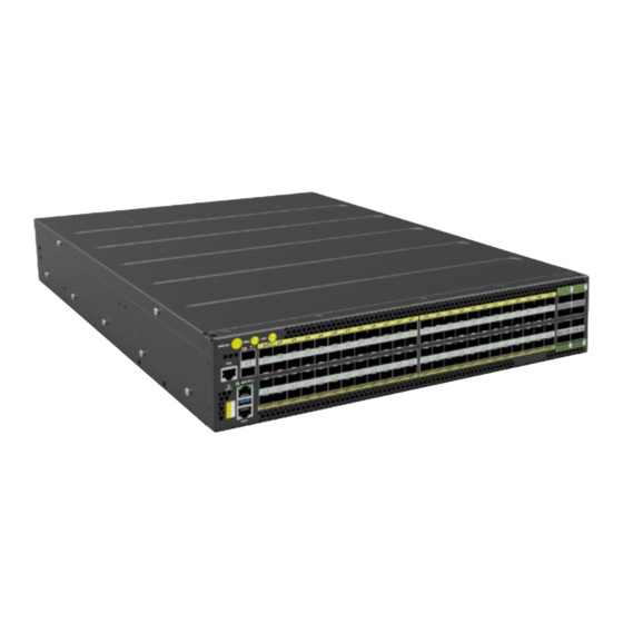
- Page 1 S9601-104BC Open Aggregation Router Hardware Installation Guide R1.1...
-
Page 2: Table Of Contents
Connecting the GNSS Interface ..................... 27 Connecting the 1PPS Interface ....................27 Connecting the 10MHz Interface ................... 28 Connecting the Transceiver ....................28 13 Cautions and Regulatory Compliance Statements .............. 29 Cautions and Regulatory Compliances .................. 29 S9601-104BC Hardware Installation Guide | i... -
Page 3: Overview
5G mobile Ethernet network. Due to its versatility, the S9601-104BC can be positioned in different parts of the network to perform aggregation, such as in the backhaul to aggregate BBU pooling or even as a Broadband Network Gateway (BNG) within the central office. -
Page 4: Preparation
PC with terminal emulation software. Refer to the "Initial System Setup" section for details. • Baud rate: 115200 bps • Data bits: 8 • Parity: None • Stop bits: 1 • Flow control: None S9601-104BC Hardware Installation Guide | 2... -
Page 5: Installation Environment Requirements
1.19 inches (3cm). Therefore, to accommodate the fan and power supply handles, a minimum space clearance of 6 inches (15.2cm) is needed at the back of the S9601-104BC. A total minimum reserve depth of 24 inches (60.96cm) is required. -
Page 6: Preparation Check List
S9601-104BC requires 2RU (3.45”/8.8cm) in height, 19” (48.3cm) in width, and need a minimum reserve depth of 24 inches (60.96cm) Thermal requirements S9601-104BC working temperature is 0 to 50°C (32°F to 122°F), airflow direction is front-to-back Installation tools required #2 Philips Screwdriver, 6-AWG yellow-and-green wire stripper, and... -
Page 7: Package Contents
1.43lb (650g)/ 2 pcs 72.05” (1830mm) 2 pcs 0.71lb (325g)/1 pcs (AC version only) USB 3.0 Cable 7.87” (200mm) 1 set 0.037lb (17.2g)/1 pcs SMB to BNC 300mm 2 set 0.039lb (18g)/1 set Converter Cable S9601-104BC Hardware Installation Guide | 5... -
Page 8: Component Physical Information
RJ45 to DB9 female cable 0.23lb (105g) AC power cord (AC version only) 0.77lb (350g) S9601-104BC (W x D x H) 17.16” x 17.32” x 3.45” (436 x 440 x 87.7mm) Dimension PSU (W x D x H) 2.89” x 7.28” x 1.57” (73.5 x 185 x 40mm) Fan (W x D x H) 3.2”... -
Page 9: Identifying Your System
4 Identifying Your System S9601-104BC Overview Figure 4. PSU Overview Power supply unit (PSU) with 1+1 Redundancy. Hot swappable, field replaceable unit (FRU). AC Version: Figure 5. S9601-104BC Hardware Installation Guide | 7... -
Page 10: Fan Overview
DC Version: Figure 6. Fan Overview 3+1 Redundant, hot swappable, field replaceable unit (FRU). Figure 7. S9601-104BC Hardware Installation Guide | 8... -
Page 11: Port Overview
Port Overview Port ID Form Factor Maximum Support Distance Support Speed 0 ~ 95 SFP28 Up to 24.85mi(40km) 1/10/25G 96 ~ 99 QSFP28 Up to 49.7mi(80km) 40/100G 100~106 QSFP56 Up to 49.7mi(80km) 40/100/200G Figure 8. S9601-104BC Hardware Installation Guide | 9... -
Page 12: Rack Mounting
Make sure the locking screw of the inner rail is positioned at the front of the chassis. 2.2 After the attachment pins are secured to the inner rail, lock the inner rail to the chassis using two M4 screws (one on each chassis side). S9601-104BC Hardware Installation Guide | 10... - Page 13 4.4 Push the blue release tab on each rail to unlock the rails and slide the chassis all the way into the rack. 4.5 Lock the chassis into place by using the screw on the front of the inner rail. S9601-104BC Hardware Installation Guide | 11...
- Page 14 Figure 12. S9601-104BC Hardware Installation Guide | 12...
-
Page 15: Installing Fan Modules
5. An audible click will be heard when the fan module is installed correctly. The fan module will not go in all the way if it is installed in the wrong direction. Figure 15. S9601-104BC Hardware Installation Guide | 13... -
Page 16: Installing Power Supply Units
1. Locate the red release tab on the PSU. Then press and hold down the release tab to unlock the PSU. 2. While holding down the red release tab, grip the PSU's handle and firmly pull it out of the power bay. DC Version: AC Version: Figure 17. S9601-104BC Hardware Installation Guide | 14... - Page 17 5. An audible click will be heard when the PSU is installed correctly. The PSU will not go in all the way if it is in the wrong direction. DC Version: AC Version: Figure 18. S9601-104BC Hardware Installation Guide | 15...
-
Page 18: Grounding The Router
4. Using a crimping tool, firmly secure the grounding wire to the grounding lug. Figure 19. 5. Locate the designated location for securing the grounding lug, which is located on the rear of the router and remove the protective label. S9601-104BC Hardware Installation Guide | 16... - Page 19 Figure 20. 6. Using 2 M4 screws and 4 washers (provided with the package contents), firmly lock the grounding lug to the designated grounding location on the router. S9601-104BC Hardware Installation Guide | 17...
-
Page 20: Connecting Power
Also, please ensure that both PSUs have been properly installed before powering up the equipment, as the S9601-104BC is designed to support 1 + 1 power redundancy. 2. Attach the DC power cables to the lugs. - Page 21 Use a heat source to secure the heat shrink tubing in place. Allow the heat shrink tubing to cool before attaching the DC power cable. An example of the installed DC version with insulation material as below. Figure 23. S9601-104BC Hardware Installation Guide | 19...
-
Page 22: Ac Version
Also, please ensure that both PSUs have been properly installed before powering up the equipment, as the S9601-104BC is designed to support 1 + 1 power redundancy. 2. Attach the power cable. - Page 23 4. Verify that the power supply is operating. If connected correctly, when turned on, the LED on the PSU will light up with a solid Green color designating normal operation. S9601-104BC Hardware Installation Guide | 21...
-
Page 24: Verifying System Operation
One or more FAN module(s) need service No Power Solid Green PSU0 is working normal Solid Amber PSU0 fail (PSU0 need service) No Power Solid Green PSU1 is working normal Solid Amber PSU 1 fail (PSU1 need service) S9601-104BC Hardware Installation Guide | 22... -
Page 25: Psu Fru Led
Additional information about fan status can be obtained by the LEDs located on the fan itself. LED Condition Equipment Status No input power to all power supplies Green Fan FRU function normal Amber Fan FRU abnormal, service is required S9601-104BC Hardware Installation Guide | 23... -
Page 26: Initial System Setup
USB cable provided in the packaging contents. Download the suitable driver for your operating system (OS) using the URL below: • https://www.silabs.com/products/development-tools/software/usb-to-uart-bridge- vcp-drivers • https://www.silabs.com/ and search for CP210X Figure 27. S9601-104BC Hardware Installation Guide | 24... - Page 27 After the connection is established, a prompt for the username and password displays. Enter the username and password to access the CLI. The username and password should be provided by the Network Operating System (NOS) vendor. S9601-104BC Hardware Installation Guide | 25...
-
Page 28: Cable Connections
1. Connect one end of a straight-through Ethernet cable to the GNSS unit 2. Connect the other end of the straight-through Ethernet cable to the port marked “TOD” located on the front panel of the router. Figure 29. S9601-104BC Hardware Installation Guide | 26... -
Page 29: Connecting The Gnss Interface
Connect an external GNSS antenna with an impedance of 50 ohms to the port marked “GNSS ANT” located on the front panel of the router. Figure 30. Connecting the 1PPS Interface Connect an external 1PPS cable with an impedance of 50 ohms to the port labelled “ 1PPS”. Figure 31. S9601-104BC Hardware Installation Guide | 27... -
Page 30: Connecting The 10Mhz Interface
1. Remove the new transceiver from its protective packaging. 2. Remove the protective plug from the transceiver itself. 3. Place the bail (wire handle) in the unlocked position and align the transceiver with the port. S9601-104BC Hardware Installation Guide | 28... -
Page 31: Cautions And Regulatory Compliance Statements
Warning: This equipment must be grounded. Do not defeat the ground conductor or operate the equipment without correctly grounding the equipment. If there is any uncertainty about the integrity of the equipment's grounding, please contact the electrical inspection authority or a certified electrician. S9601-104BC Hardware Installation Guide | 29... - Page 32 This is a Class A product based on the standard of the Voluntary Control Council for Interference by Information Technology Equipment (VCCI). If this equipment is used in a domestic environment, radio disturbance may arise. When such trouble occurs, the user may be required to take corrective actions. S9601-104BC Hardware Installation Guide | 30...
- Page 33 (Type 2, 4, or 4a ports as described in GR-1089) and require isolation from the exposed OSP cabling. The addition of Primary Protectors is not sufficient protection in order to connect these interfaces metallically to an OSP wiring system.” S9601-104BC Hardware Installation Guide | 31...
- Page 34 www.ufispace.com...
Need help?
Do you have a question about the S9601-104BC and is the answer not in the manual?
Questions and answers