Table of Contents
Advertisement
Quick Links
Advertisement
Table of Contents

Related Manuals for UfiSpace S9705-48D


Summary of Contents for UfiSpace S9705-48D
- Page 1 S9705-48D Core/Edge Router Hardware Installation Guide R1.0...
-
Page 2: Table Of Contents
11 Initial System Setup ......................24 12 Cable Connections ....................... 25 Connecting the USB Extender Cable ..................25 Connecting the Transceiver ....................25 13 Cautions and Regulatory Compliance Statements ............... 27 Cautions and Regulatory Compliances ................27 S9705-48D Hardware Installation Guide | i... -
Page 3: Overview
S9705-48D is a robust fabric switch that used to interconnect the S9710-76D, S9700-53DX and/or S9700-23D routers into pay-as-you-grow cluster sizes. Suitable for core networking, the S9705-48D is one of the essential building blocks to provide carriers with a better solution in place of the traditional chassis. -
Page 4: Preparation
PC with terminal emulation software. Refer to the "Initial System Setup" section for details. • Baud rate: 115200 bps • Data bits: 8 • Parity: None • Stop bits: 1 • Flow control: None S9705-48D Hardware Installation Guide | 2... -
Page 5: Installation Environment Requirements
FRU is 1 inch (2.5cm) and the handle of the PSU FRU is 1.5 inches (3.8cm). Therefore, to accommodate the fan, power supply handles, airflow and cabling, a minimum space clearance of 6 inches (15.2cm) is needed at front and back of the S9705-48D. A total minimum reserve depth of 42 inches (106.6cm) is required. -
Page 6: Preparation Check List
AC version: 200 to 240V AC, 12.5 x 2 ampere maximum Installation spacing requirement S9705-48D chassis spacing requires a height of 2RU (3.45”/8.8cm), a width of 19” (48.3cm), and a depth of 42 inches (106.6cm) Thermal requirement S9705-48D working temperature is 0°C to 45°C (32°F to 113°F),... -
Page 7: Package Contents
Adjustable Mounting (771 x 44 x 22mm) 2 pcs Rail (for 4 post) (3.5lbs (1.6kg)/1 pcs) (22”~33” rack depth) Screw Kit 2 sets 2 x Screw M4.0*L5.5mm 0.004lbs (1.9g)/1 set (for Rack Mount Rail) S9705-48D Hardware Installation Guide | 5... -
Page 8: Component Physical Information
RJ45 to DB9 Female cable 0.23lbs (105g) AC power cord (AC version only) 0.70lbs (318g) S9705-48D (W x D x H) 17.16” x 30” x 3.45” (436 x 762 x 87.7mm) Dimension PSU (W x D x H) 1.99 x 14.17” x 1.58” (50.5 x 360 x 40mm) Fan (W x D x H) 3.15”... -
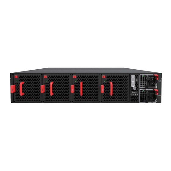
Page 9: Identifying Your System
4 Identifying Your System S9705-48D Overview Figure 4. PSU Overview Power supply unit (PSU) with 1+1 Redundancy. Hot swappable, field replaceable unit (FRU). AC Version: Figure 5. S9705-48D Hardware Installation Guide | 7... -
Page 10: Fan Overview
DC Version: Figure 6. Fan Overview 3+1 Redundant, hot swappable, field replaceable unit (FRU). Figure 7. S9705-48D Hardware Installation Guide | 8... -
Page 11: Port Overview
Port ID Form Factor Maximum Support Distance Support Speed 0 ~ 47 QSFP-DD 328ft (100m) 400GE The 400G fabric ports of the S9705-48D can only be used to interconnect the S9700 Series routers. Figure 8. S9705-48D Hardware Installation Guide | 9... -
Page 12: Rack Mounting
Make sure the locking screw of the inner rail is positioned at the front of the chassis. 2.2 After the attachment pins are secured to the inner rail, lock the inner rail to the chassis using two M4 screws (one on each chassis side). S9705-48D Hardware Installation Guide | 10... - Page 13 4.4 Push the blue release tab on each rail to unlock the rails and slide the chassis all the way into the rack. 4.5 Lock the chassis into place by using the screw on the front of the inner rail. S9705-48D Hardware Installation Guide | 11...
- Page 14 Figure 12. S9705-48D Hardware Installation Guide | 12...
-
Page 15: Installing Fan Modules
5. An audible click will be heard when the fan module is installed correctly. The fan module will not go in all the way if it is installed in the wrong direction. Figure 15. S9705-48D Hardware Installation Guide | 13... -
Page 16: Installing Power Supply Units
1. Locate the release tab on the PSU. Then press and hold down the release tab to unlock the PSU. 2. While holding down the release tab, grip the PSU's handle and firmly pull it out of the power bay. DC Version: AC Version: Figure 17. S9705-48D Hardware Installation Guide | 14... - Page 17 4. Carefully slide the new PSU into the power bay and gently push until it is flush with the case. 5. An audible click will be heard when the PSU is installed correctly. The PSU will not go in all the way if it is in the wrong direction. Figure 18. S9705-48D Hardware Installation Guide | 15...
-
Page 18: Grounding The Router
3. Insert the exposed grounding wire all the way into the hole of the grounding lug (provided with package contents). 4. Using a crimping tool, firmly secure the grounding wire to the grounding lug. Figure 19. S9705-48D Hardware Installation Guide | 16... - Page 19 Figure 20. 6. Using 2 M4 screws and 4 washers (provided with the package contents), firmly lock the grounding lug to the designated grounding location on the router. Figure 21. S9705-48D Hardware Installation Guide | 17...
-
Page 20: Connecting Power
Also, please ensure that both PSUs have been properly installed before powering up the equipment, as the S9705-48D is designed to support 1 + 1 power redundancy. 2. Attach the DC power cables to the lugs. - Page 21 Secure the two-hole lug (with the DC power cable attached) to the terminal block as depicted in the following figure. S9705-48D Hardware Installation Guide | 19...
-
Page 22: Ac Version
Also, please ensure that both PSUs have been properly installed before powering up the equipment, as the S9705-48D is designed to support 1 + 1 power redundancy. 2. Attach the power cable. - Page 23 If connected correctly, when turned on, the LED on the PSU will light up with a solid Green color designating normal operation. If only a 110V AC power source is available, the S9705-48D can still be powered with both PSUs providing 1000 watts each for a total output of 2000 watts. However, in this case, if one PSU stops functioning, the power output would be inefficient to sustain the router’s...
-
Page 24: Verifying System Operation
Solid Amber PSU 0 fail (PSU0 need service) Blinking Amber Reserved No Power Solid Green PSU 1 is working well Blinking Green Reserved Solid Amber PSU 1 fail (PSU1 need service) Blinking Amber Reserved S9705-48D Hardware Installation Guide | 22... -
Page 25: Psu Fru Led
Additional information about fan status can be obtained by the LEDs located on the fan itself. LED Condition Equipment Status No input power to all power supplies Green Fan FRU function normal Amber Fan FRU abnormal, service is required S9705-48D Hardware Installation Guide | 23... -
Page 26: Initial System Setup
Download the suitable driver for your operating system (OS) using the URL below: • https://www.silabs.com/products/development-tools/software/usb-to-uart-bridge- vcp-drivers • https://www.silabs.com/ and search for CP210X Figure 29. 2. Check for serial control availability. Disable any serial communication programs running on the computer such as synchronization programs to prevent interference. S9705-48D Hardware Installation Guide | 24... -
Page 27: Cable Connections
Read the following guidelines before connecting the transceiver: • Before installing the router, take into consideration rack space requirements for cable management and plan accordingly. • It is recommended to use hook-and-loop style straps to secure and organize the cables. S9705-48D Hardware Installation Guide | 25... - Page 28 3. Place the bail (wire handle) in the unlocked position and align the transceiver with the port. 4. Slide the transceiver into the port and gently push until it is secured in place. An audible click can be heard when the transceiver is secured in the port. S9705-48D Hardware Installation Guide | 26...
-
Page 29: Cautions And Regulatory Compliance Statements
Avertissement: Ne pas utiliser d’instruments optiques pour voir la sortie du laser. L’utilisation de instruments optiques pour afficher la sortie laser augmente les risques oculaires. Utilisez uniquement UL/CSA, IEC/EN60825-1 /-2 reconnu modules enfichables. S9705-48D Hardware Installation Guide | 27... - Page 30 This is a Class A product based on the standard of the Voluntary Control Council for Interference by Information Technology Equipment (VCCI). If this equipment is used in a domestic environment, radio disturbance may arise. When such trouble occurs, the user may be required to take corrective actions. S9705-48D Hardware Installation Guide | 28...
- Page 31 (Type 2, 4, or 4a ports as described in GR-1089) and require isolation from the exposed OSP cabling. The addition of Primary Protectors is not sufficient protection in order to connect these interfaces metallically to an OSP wiring system.” S9705-48D Hardware Installation Guide | 29...
- Page 32 www.ufispace.com...
Need help?
Do you have a question about the S9705-48D and is the answer not in the manual?
Questions and answers