Table of Contents
Advertisement
Quick Links
Advertisement
Table of Contents

Related Manuals for UfiSpace S9701-82DC


Summary of Contents for UfiSpace S9701-82DC
- Page 1 S9701-82DC Core/Edge Router Hardware Installation Guide R1.0...
-
Page 2: Table Of Contents
Connecting the 1PPS Interface .................... 26 Connecting the 10MHz Interface ..................27 Connecting the Transceiver ....................27 13 Cautions and Regulatory Compliance Statements .............. 28 Cautions and Regulatory Compliances ................28 Installation Location Statement ..................30 S9701-82DC Hardware Installation Guide | i... -
Page 3: Overview
5G mobile Ethernet network. Due to its flexible configuration, the S9701-82DC can be positioned in different parts of the network to perform aggregation, such as in data center for massive server aggregation or even as a Broadband Network Gateway (BNG) within the central office. -
Page 4: Preparation
PC with terminal emulation software. Refer to the "Initial System Setup" section for details. • Baud rate: 115200 bps • Data bits: 8 • Parity: None • Stop bits: 1 • Flow control: None S9701-82DC Hardware Installation Guide | 2... -
Page 5: Installation Environment Requirements
1.1 inches (2.7cm). Therefore, to accommodate the fan handles, power supply handles, airflow and cabling, a minimum space clearance of 6 inches (15.2cm) is needed at front and back of the S9701-82DC. A total minimum reserve depth of 36 inches (91.4cm) is required. -
Page 6: Preparation Check List
S9701-82DC chassis spacing requires a height of 2RU (3.45”/8.8cm), a width of 19” (48.3cm), and a depth of 36 inches (91.4cm) Thermal requirement S9701-82DC working temperature is 0°C to 45°C (32°F to 113°F), airflow direction is front-to-back Installation tools required... -
Page 7: Package Contents
2 Sets 0.004lbs(1.9g)/ 1 set (for Mounting Rail) SMB to BNC Converter 3.94” to 11.8” 2 pcs 0.035lbs (16g)/1 pcs Cable (10 to 30cm) Power Cord 2pcs 70.87” (1800mm) 0.70lbs (318g)/2pcs (AC version only) S9701-82DC Hardware Installation Guide | 5... -
Page 8: Component Physical Information
AC power cord (AC version only) 0.70lbs (318g) SMB to BNC converter cable 0.07lbs (32g) S9701-82DC (W x D x H) 17.16” x 24” x 3.45” (436 x 609.6 x 87.7mm) Dimension PSU (W x D x H) 1.99 x 12.64” x 1.58” (50.5 x 321 x 40mm) Fan (W x D x H) 3.15”... -
Page 9: Identifying Your System
4 Identifying Your System S9701-82DC Overview Figure 4. PSU Overview Power supply unit (PSU) with 1+1 Redundancy. Hot swappable, field replaceable unit (FRU). AC Version: Figure 5. S9701-82DC Hardware Installation Guide | 7... -
Page 10: Fan Overview
DC Version: Figure 6. Fan Overview 3+1 Redundant, hot swappable, field replaceable unit (FRU). Figure 7. S9701-82DC Hardware Installation Guide | 8... -
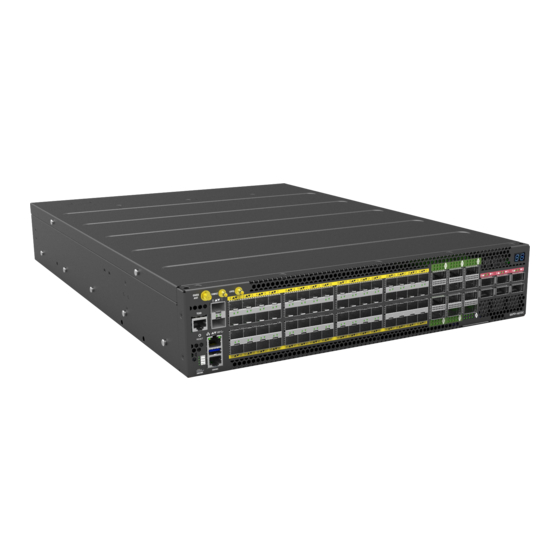
Page 11: Port Overview
The service ports (labelled in yellow and green in figure below) are ethernet packet based ports used to connect to servers and other networking equipment. The fabric ports (labelled in red in figure below) are only for connecting with fabric ports of the S9705-48D fabric switch. Figure 8. S9701-82DC Hardware Installation Guide | 9... -
Page 12: Rack Mounting
Make sure the locking screw of the inner rail is positioned at the front of the chassis. 2.2 After the attachment pins are secured to the inner rail, lock the inner rail to the chassis using two M4 screws (one on each chassis side). Figure 10. S9701-82DC Hardware Installation Guide | 10... - Page 13 4.4 Push the blue release tab on each rail to unlock the rails and slide the chassis all the way into the rack. 4.5 Lock the chassis into place by using the screw on the front of the inner rail. Figure 12. S9701-82DC Hardware Installation Guide | 11...
-
Page 14: Installing Fan Modules
5. An audible click will be heard when the fan module is installed correctly. The fan module will not go in all the way if it is installed in the wrong direction. Figure 15. S9701-82DC Hardware Installation Guide | 12... -
Page 15: Installing Power Supply Units
1. Locate the release tab on the PSU. Then press and hold down the release tab to unlock the PSU. 2. While holding down the release tab, grip the PSU's handle and firmly pull it out of the power bay. DC Version: AC Version: Figure 17. S9701-82DC Hardware Installation Guide | 13... - Page 16 4. Carefully slide the new PSU into the power bay and gently push until it is flush with the case. 5. An audible click will be heard when the PSU is installed correctly. The PSU will not go in all the way if it is in the wrong direction. Figure 18. S9701-82DC Hardware Installation Guide | 14...
-
Page 17: Grounding The Router
3. Insert the exposed grounding wire all the way into the hole of the grounding lug (provided with package contents). 4. Using a crimping tool, firmly secure the grounding wire to the grounding lug. Figure 19. S9701-82DC Hardware Installation Guide | 15... - Page 18 Figure 20. 6. Using 2 M4 screws and 4 washers (provided with the package contents), firmly lock the grounding lug to the designated grounding location on the router. Figure 21. S9701-82DC Hardware Installation Guide | 16...
-
Page 19: Connecting Power
Also, please ensure that both PSUs have been properly installed before powering up the equipment, as the S9701-82DC is designed to support 1 + 1 power redundancy. 2. Attach the DC power cables to the lugs. - Page 20 Use a heat source to secure the heat shrink tubing in place. Allow the heat shrink tubing to cool before attaching the DC power cable. An example of the installed DC version with insulation material as below. Figure 24. S9701-82DC Hardware Installation Guide | 18...
- Page 21 6. Verify that the power supply is operating. If connected correctly, when turned on, the LED on the PSU will light up with a Green color designating normal operation. S9701-82DC Hardware Installation Guide | 19...
-
Page 22: Ac Version
If connected correctly, when turned on, the LED on the PSU will light up with a solid Green color designating normal operation. If only a 110V AC power source is available, the S9701-82DC can still be powered with both PSUs providing 1000 watts each for a total output of 2000 watts. However, in this case, if one PSU stops functioning, the power output would be inefficient to sustain the router’s... -
Page 23: Verifying System Operation
Solid Amber One or more FAN module(s) need service Blinking Amber Reserved No Power Solid Green PSU 0 is working well Blinking Green Reserved Solid Amber PSU 0 fail (PSU0 need service) Blinking Amber Reserved S9701-82DC Hardware Installation Guide | 21... -
Page 24: Psu Fru Led
Additional information about fan status can be obtained by the LEDs located on the fan itself. LED Condition Equipment Status No input power to all power supplies Green Fan FRU function normal Amber Fan FRU abnormal, service is required S9701-82DC Hardware Installation Guide | 22... -
Page 25: Initial System Setup
USB cable provided in the packaging contents. Download the suitable driver for your operating system (OS) using the URL below: • https://www.silabs.com/products/development-tools/software/usb-to-uart-bridge- vcp-drivers • https://www.silabs.com/ and search for CP210X Figure 29. S9701-82DC Hardware Installation Guide | 23... - Page 26 After the connection is established, a prompt for the username and password displays. Enter the username and password to access the CLI. The username and password should be provided by the Network Operating System (NOS) vendor. S9701-82DC Hardware Installation Guide | 24...
-
Page 27: Cable Connections
1. Connect one end of a straight-through Ethernet cable to the GNSS unit 2. Connect the other end of the straight-through Ethernet cable to the port marked “TOD” located on the front panel of the router. Figure 31. S9701-82DC Hardware Installation Guide | 25... -
Page 28: Connecting The Gnss Interface
Connect an external 1PPS cable with an impedance of 50 ohms to the port labelled “1PPS”. If the connector is not same type as SMB, please use the converter cable in the accessory list to convert to BNC type. Figure 33. S9701-82DC Hardware Installation Guide | 26... -
Page 29: Connecting The 10Mhz Interface
3. Place the bail (wire handle) in the unlocked position and align the transceiver with the port. 4. Slide the transceiver into the port and gently push until it is secured in place. An audible click can be heard when the transceiver is secured in the port. S9701-82DC Hardware Installation Guide | 27... -
Page 30: Cautions And Regulatory Compliance Statements
Avertissement: Ne pas utiliser d’instruments optiques pour voir la sortie du laser. L’utilisation de instruments optiques pour afficher la sortie laser augmente les risques oculaires. Utilisez uniquement UL/CSA, IEC/EN60825-1 /-2 reconnu modules enfichables. S9701-82DC Hardware Installation Guide | 28... - Page 31 Le présent appareil numérique n’émet pas de bruits radioélectriques dépassant les limites applicables aux appareils numériques de la class A prescrites dans le Règlement sur le brouillage radioélectrique édicté par le ministère des Communications du Canada S9701-82DC Hardware Installation Guide | 29...
-
Page 32: Installation Location Statement
Only afforded by the use of a tool or lock and key, or other means of security, and controlled by the authority responsible for the location. Suitable for installation in Information Technology Rooms in accordance with Article 645 of the National Electrical Code and NFPA 75. S9701-82DC Hardware Installation Guide | 30... - Page 33 www.ufispace.com...
Need help?
Do you have a question about the S9701-82DC and is the answer not in the manual?
Questions and answers