
Related Manuals for Artecta Image Spot 170 FC V1


Summary of Contents for Artecta Image Spot 170 FC V1
- Page 1 USER MANUAL ENGLISH Image Spot 170 FC Product code: A0690111 Highlite International B.V. – Vestastraat 2 – 6468 EX – Kerkrade – the Netherlands...
- Page 2 Image Spot 170 FC Preface Thank you for purchasing this Artecta product. The purpose of this user manual is to provide instructions for the correct and safe use of this product. Keep the user manual for future reference as it is an integral part of the product. The user manual shall be stored at an easily accessible location.
-
Page 3: Table Of Contents
Image Spot 170 FC Table of contents Introduction ................................4 Before Using the Product ..........................4 Intended Use ............................... 4 Product Lifespan ..............................4 LEDs Lifespan ............................... 4 Text Conventions ..............................5 Symbols and Signal Words ..........................5 Symbols on the Information Label ........................5 Safety .................................. - Page 4 Image Spot 170 FC Disp Time (Display Time) ........................29 WDMX Reset ............................29 Signal ..............................30 Language ............................30 Info .................................30 CCT (Correlated Color Temperature Control) ..................31 Preset Color .............................31 DMX Channels ..............................32 HSIC (8 CH) ..............................32 SIMPLE (8 CH), COLOR 8BIT (11 CH), COLOR 16BIT (17 CH) ..............33 Rotating Gobo Holder .............................35 Replacing a Gobo from the Rotating Gobo Wheel ................35 Gobo Size ..............................37...
-
Page 5: Introduction
Image Spot 170 FC Introduction Before Using the Product Important Read and follow the instructions in this user manual before installing, operating or servicing this product. The manufacturer will not accept liability for any resulting damages caused by the non-observance of this manual. -
Page 6: Text Conventions
Image Spot 170 FC Text Conventions Throughout the user manual the following text conventions are used: ● Buttons: All buttons are in bold lettering, for example “Press the UP/DOWN buttons” ● References: References to chapters and parts of the device are in bold lettering, for example: “Refer to 2. -
Page 7: Safety
Image Spot 170 FC Safety Important Read and follow the instructions in this user manual before installing, operating or servicing this product. The manufacturer will not accept liability for any resulting damages caused by the non-observance of this manual. Warnings and Safety Instructions DANGER Danger for children For adult use only. - Page 8 Image Spot 170 FC ● Make sure that the cable run is not too heavy. A heavy cable run can cause damage to the connectors. If the connectors are damaged, their ingress protection (IP) can deteriorate. WARNING Risk of epileptic shock Strobe lighting can trigger seizures in photosensitive epilepsy.
-
Page 9: Requirements For The User
Image Spot 170 FC Attention Before each use, examine the device visually for any defects. Make sure that: ● All screws used for installing the device or parts of the device are tightly fastened and are not corroded. ● The safety devices are not damaged. ●... -
Page 10: Description Of The Device
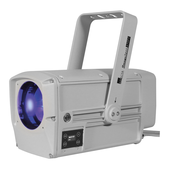
Image Spot 170 FC Description of the Device The Artecta Image Spot 170 FC is a 170 Watt gobo projector spot with a powerful RGBAL LED in an IP66 die-cast aluminium housing, suitable for indoor and outdoor applications. It features a bi-rotational gobo and 16-bit color control, manually adjustable beam angle and focus, manual framing system, adjustable PWM and adjustable fan modes for quiet operation, as well as a strobe function. -
Page 11: Product Specifications
Image Spot 170 FC Product Specifications Model: Image Spot 170 FC Electrical: Input voltage: 100–240 V AC, 50/60 Hz Power consumption: 200 W Physical: Dimensions: 454 x 206 x 201 mm (LxWxH) Weight: 7,9 kg Optics: Light source: 170W RGBAL LED Dimmer: 0–100 % Strobe:... -
Page 12: Optional Accessories
Image Spot 170 FC Optional Accessories The Image Spot 170 FC is delivered with accessories. You can additionally purchase the following accessories: ● Product code: 43600 IP65 Power Extension cable 1,5 m ● Product code: 43601 IP65 Power Extension cable 5 m ●... -
Page 13: Installation
Image Spot 170 FC Installation Safety Instructions for Installation WARNING Incorrect installation can cause serious injuries and damage of property. If trussing systems are used, installation must be carried out only by instructed or skilled persons. Follow all applicable European, national and local safety regulations concerning rigging and trussing. Personal Protective Equipment During installation and rigging wear personal protective equipment in compliance with the national and site-specific regulations. -
Page 14: Rigging
Image Spot 170 FC Rigging The device can be positioned on a flat surface or mounted to a truss or other rigging structure in any orientation. Make sure that all loads are within the pre-determined limits of the supporting structure. CAUTION Restrict the access under the work area during rigging and/or derigging. -
Page 15: Angle Adjustment
Image Spot 170 FC Angle Adjustment You can adjust the angle of the device with the adjustment screw (04). 01) Turn the adjustment screw (04) counterclockwise to release it. 02) Tilt the device to the desired angle (see Fig. 07). 03) Turn the adjustment screw (04) clockwise to tighten it. -
Page 16: Connecting To Power Supply
Image Spot 170 FC Connecting to Power Supply DANGER Electric shock caused by short-circuit The device accepts AC mains power at 100–240 V and 50/60 Hz. Do not supply power at any other voltage or frequency to the device. This device falls under IEC protection class I. Make sure that the device is always electrically connected to the ground (earth). -
Page 17: Setup
Image Spot 170 FC Setup Warnings and Precautions Attention Connect all data cables before supplying power. Disconnect power supply before connecting or disconnecting data cables. Stand-alone Setup When the Image Spot 170 FC is not connected to a controller or to other devices, it functions as a stand- alone device. -
Page 18: Dmx Cables
Image Spot 170 FC DMX Cables Shielded twisted-pair cables with 3-pin XLR connectors must be used for reliable DMX connection. You can purchase DMX cables directly from your Highlite International dealer or make your own cables. If you use 3-pin XLR audio cables for DMX data transmission, this may lead to signal degradation and unreliable operation of the DMX network. -
Page 19: Dmx Linking
Image Spot 170 FC DMX Linking To connect multiple devices on one DMX data link, follow the steps below: 01) Use the supplied 3-pin XLR to special 3-pin data cable to connect the DMX OUT connector of the lighting controller to the DMX IN connector of the first device. 02) Connect the first device’s DMX OUT connector to the second device’s DMX IN connector. -
Page 20: Operation
Image Spot 170 FC Operation Safety Instructions for Operation Attention This device must be used only for the purposes it is designed for. This device is intended for professional use as an outdoor spot. It is not suitable for households and for general lighting. -
Page 21: Control Panel
Image Spot 170 FC Control Panel A) MENU button LED display C) UP button D) DOWN button ENTER button Fig. 11 ● Use the MENU function in each menu to exit the current submenu and to return to the Main Menu. ●... -
Page 22: Menu Overview
Image Spot 170 FC Menu Overview Product code: A0690111... - Page 23 Image Spot 170 FC Product code: A0690111...
- Page 24 Image Spot 170 FC Product code: A0690111...
-
Page 25: Main Menu Options
Image Spot 170 FC Main Menu Options The main menu has the following options: 01) Press the MENU button to open the main menu. 02) Press the UP/DOWN buttons to navigate through the main menu. ● Static: See 6.6.1. Static ●... -
Page 26: Run Mode
Image Spot 170 FC Run Mode In this menu you can set the control mode of the device. Press the UP/DOWN buttons to toggle between the following 2 options: ● DMX: The device will operate in DMX Mode ● SLAVE: The device will operate as a slave in Master/Slave Mode. -
Page 27: Edit
Image Spot 170 FC Edit In this menu you can edit the custom programs thus creating your own custom show. Press the UP/DOWN buttons to select the custom program you want to edit (PROGRAM1–2) or UPLOAD, see 6.6.6.1. Upload on page 27. Press the ENTER button to confirm. -
Page 28: Upload
Image Spot 170 FC Upload In this submenu you can export the custom programs from the master device to the connected slave devices. Select UPLOAD and press the ENTER button to open the submenu. Enter the password, pressing the buttons in the following order: UP, DOWN, UP, DOWN. Press the ENTER button to confirm. -
Page 29: Reset
Image Spot 170 FC Reset In this submenu you can restore the default factory settings and reset the custom programs. Select RESET and press the ENTER button to open the submenu. Enter the password, pressing the buttons in the following order: UP, DOWN, UP, DOWN. Press the ENTER button to confirm. -
Page 30: Pwm Rate
Image Spot 170 FC PWM Rate In this submenu you can set the PWM (Pulse Width Modulation) frequency. Select PWM RATE and press the ENTER button to open the submenu. Press the UP/DOWN buttons to select the desired PWM frequency. The available options are: 1200 Hz, 2400 Hz, 4000 Hz, 6000 Hz and 25000 Hz. -
Page 31: Signal
Image Spot 170 FC Signal In this submenu you can set the signal preferences when wireless DMX is enabled. Press the UP/DOWN buttons to select one of the following 2 options: ● XLRDMX: DMX signal is only received via wired XLR cable ●... -
Page 32: Cct (Correlated Color Temperature Control)
Image Spot 170 FC CCT (Correlated Color Temperature Control) In this menu you can calibrate the color temperature. Press the UP/DOWN buttons to scroll through the following options: Press the ENTER button to confirm. Preset Color In this menu you can select a preset color mix. Press the UP/DOWN buttons to select one of the 48 presets: Press the ENTER button to confirm. -
Page 33: Dmx Channels
Image Spot 170 FC DMX Channels HSIC (8 CH) 8 CH Function Value Setting (HSIC) Intensity 000–255 From low to high intensity (0–100 %) 000–255 From low to high intensity (0–100 %) Hue Fine 000–255 From low to high intensity (0–100 %) Saturation 000–255 From low to high intensity (0–100 %) -
Page 34: Simple (8 Ch), Color 8Bit (11 Ch), Color 16Bit (17 Ch)
Image Spot 170 FC SIMPLE (8 CH), COLOR 8BIT (11 CH), COLOR 16BIT (17 CH) 11 CH 17 CH 8 CH (COLOR (COLOR Function Value Setting (SIMPLE) 8BIT) 16BIT) Master Dimmer 000–255 From low to high intensity (0–100 %) Dimmer Fine 000–255 From low to high intensity (0–100 %) 000–255... - Page 35 Image Spot 170 FC 11 CH 17 CH 8 CH (COLOR (COLOR Function Value Setting (SIMPLE) 8BIT) 16BIT) 221–225 Color 43 Flesh Pink L192 226–230 Color 44 Special Rose Pink L332 231–235 Color 45 Moroccan Pink L790 236–240 Color 46 Pink L157 241–245...
-
Page 36: Rotating Gobo Holder
Image Spot 170 FC Rotating Gobo Holder Fig. 12 Replacing a Gobo from the Rotating Gobo Wheel DANGER Electric shock caused by dangerous voltage inside There are areas within the device where dangerous touch voltage may be present. Disconnect the device from electrical power supply before service and maintenance, and when the device is not in use. - Page 37 Image Spot 170 FC Loosen the 2 screws on the gobo/shutter blade cover, as shown in Fig. 14. Gently lift the gobo/shutter blade assembly a bit up and pull it out, as shown in Fig. 15. Fig. 14 Fig. 15 Very carefully take the gobo holder out of the gobo/shutter blade assembly, as shown in Fig.
-
Page 38: Gobo Size
Image Spot 170 FC Gobo Size Gobo Fig. 17 Glass Gobo Orientation Coated glass gobos are inserted with the coating against the rim of the holder. Textured gobos are inserted with the smooth side pointing away from the holder. This provides the best results when combining rotating gobos. -
Page 39: Rdm Information
This device supports RDM. Refer to 6.8.2. Supported RDM PIDs (Parameter IDs) for more information. RDM Details ● Responder: 29B4:0CExxxxx ● Manufacturer's ID: Showtec (Highlite International B.V.) ● Manufacturer Label: Artecta ● Model Description: Image Spot 170 FC ● Model ID: ● Device Label: Image Spot 170 FC Supported RDM PIDs (Parameter IDs) -
Page 40: Troubleshooting
Image Spot 170 FC Troubleshooting This troubleshooting guide contains solutions to problems which can be carried out by an ordinary person. The device does not contain user-serviceable parts. Unauthorized modifications to the device will render the warranty void. Such modifications may result in injuries and material damage. -
Page 41: Maintenance
Image Spot 170 FC Maintenance Safety Instructions for Maintenance DANGER Electric shock caused by dangerous voltage inside Disconnect power supply before servicing or cleaning. Preventive Maintenance Attention Before each use, examine the device visually for any defects. Make sure that: ●... -
Page 42: Draining Condensation Water
Image Spot 170 FC Draining Condensation Water The Image Spot 170 FC is IP66 rated. The device can resist water jets. If the device is exposed to extreme humid conditions during servicing, condensation may collect inside the device. This can happen also during transportation, if the device is exposed to extreme temperature variations. -
Page 43: Deinstallation, Transportation And Storage
Image Spot 170 FC Deinstallation, Transportation and Storage Instructions for Deinstallation WARNING Incorrect deinstallation can cause serious injuries and damage of property. ● Let the device cool down before dismounting. ● Disconnect power supply before deinstallation. ● Always observe the national and site-specific regulations during deinstallation and derigging of the device. - Page 44 ©2023 Artecta...
Need help?
Do you have a question about the Image Spot 170 FC V1 and is the answer not in the manual?
Questions and answers