
Related Manuals for Artecta Image Spot 200


Summary of Contents for Artecta Image Spot 200
- Page 1 USER MANUAL ENGLISH Image Spot 200 Product code: A0690101 Highlite International B.V. – Vestastraat 2 – 6468 EX – Kerkrade – the Netherlands...
- Page 2 Image Spot 200 Preface Thank you for purchasing this Artecta product. The purpose of this user manual is to provide instructions for the correct and safe use of this product. Keep the user manual for future reference as it is an integral part of the product. The user manual shall be stored at an easily accessible location.
-
Page 3: Table Of Contents
Image Spot 200 Table of contents Introduction ................................4 Before Using the Product ..........................4 Intended Use ............................... 4 Product Lifespan ..............................4 LEDs Lifespan ............................... 4 Text Conventions ..............................4 Symbols and Signal Words ..........................5 Symbols on the Information Label ........................5 Safety .................................. - Page 4 Image Spot 200 Information ..............................32 DMX Channels ..............................33 , 13 Channels ...............................33 Color Wheel and Rotating Gobo wheel .....................34 Replacing a Gobo from the Rotating Gobo Wheel ................34 Gobo Size ..............................36 Glass Gobo Orientation ..........................36 RDM Information ...............................37 RDM Details ..............................37 Supported RDM PIDs (Parameter IDs) .....................37...
-
Page 5: Introduction
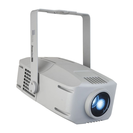
After unpacking, check the contents of the box. If any parts are missing or damaged, contact your Highlite International dealer. Your shipment includes: ● Showtec Image Spot 200 ● Special 3-pin to IEC power cable (1,35m) ● User manual Fig. -
Page 6: Symbols And Signal Words
Image Spot 200 Symbols and Signal Words Safety notes and warnings are indicated throughout the user manual by safety signs. Always follow the instructions provided in this user manual. Indicates an imminently hazardous situation which, if not avoided, will result in DANGER death or serious injury. -
Page 7: Safety
Image Spot 200 Safety Important Read and follow the instructions in this user manual before installing, operating or servicing this product. The manufacturer will not accept liability for any resulting damages caused by the non-observance of this manual. Warnings and Safety Instructions... - Page 8 Image Spot 200 ● Make sure that the cable run is not too heavy. A heavy cable run can cause damage to the connectors. If the connectors are damaged, their ingress protection (IP) can deteriorate. WARNING Risk of epileptic shock Strobe lighting can trigger seizures in photosensitive epilepsy.
-
Page 9: Requirements For The User
Image Spot 200 Make sure that: ● All screws used for installing the device or parts of the device are tightly fastened and are not corroded. ● The safety devices are not damaged. ● There are no deformations on housings, fixations and installation points. -
Page 10: Description Of The Device
Description of the Device The Artecta Image Spot 200 is a 200 watt gobo projector spot with IP65 rating and high >80 CRI, suitable for outdoor applications. Its 7 gobos + open can be projected in 7 dichroic colours + white and can be indexed, meaning the gobo's rotational position can be recalled. -
Page 11: Back View
Image Spot 200 Back View Fig. 03 04) 3-pin IP65 DMX signal connector IN 05) IP65 power IN 06) LED Display + Menu Buttons 07) Protective Vent 08) IP65 power OUT 09) 3-pin IP65 DMX signal connector OUT Product code: A0690101... -
Page 12: Product Specifications
Image Spot 200 Product Specifications Model: Image Spot 200 Electrical: Input voltage: 100–240 V AC, 50/60 Hz Power consumption: 220 W Physical: Dimensions: 477 x 318 x 418 mm (LxWxH) Weight: 15,1 kg Optics: Light source: 200W CW LED Dimmer: 0–100 %... -
Page 13: Optional Accessories
Image Spot 200 Optional Accessories The Image Spot 200 is delivered with accessories. You can additionally purchase the following accessories: ● Product code: A9920800 (IP-67 Data Extension Cable 1,5m) ● Product code: A9920801 (IP-67 Data Extension Cable 3m) ● Product code:... -
Page 14: Installation
Image Spot 200 Installation Safety Instructions for Installation WARNING Incorrect installation can cause serious injuries and damage of property. If trussing systems are used, installation must be carried out only by instructed or skilled persons. Follow all applicable European, national and local safety regulations concerning rigging and trussing. -
Page 15: Rigging
Image Spot 200 Rigging The device can be positioned on a flat surface or mounted to a truss or other rigging structure in any orientation. Make sure that all loads are within the pre-determined limits of the supporting structure. Fig. 05 CAUTION Restrict the access under the work area during rigging and/or derigging. - Page 16 Image Spot 200 To mount the device, follow the steps below: 01) Use a clamp to attach the device to the supporting structure, as shown in Fig. 05. Make sure that the device cannot move freely. 02) Secure the device with a secondary suspension, for example a safety cable. Make sure that the secondary suspension can hold 10 times the weight of the device.
-
Page 17: Angle Adjustment
Image Spot 200 Angle Adjustment You can adjust the angle of the device with the adjustment screw (03). 01) Turn the adjustment screw (03) counterclockwise to release it. 02) Tilt the device to the desired angle (see Fig. 07). 03) Turn the adjustment screw (03) clockwise to tighten it. Make sure that the device cannot move freely after the adjustment screw (03) is tightened. -
Page 18: Free-Standing Bracket Installation
Image Spot 200 Free-standing Bracket Installation 01) Put the free-standing bracket on the Image Spot 200. 02) Install all elements as shown in Fig. 08. 03) Tighten the screws. Fig. 08 Connecting to Power Supply DANGER Electric shock caused by short-circuit The device accepts AC mains power at 100–240 V and 50/60 Hz. -
Page 19: Power Linking Of Multiple Devices
Do not link more devices on one power link than the maximum recommended number. Maximum recommended number of devices: ● at 100–120 V: 6 devices Image Spot 200 ● at 200–240 V: 12 devices Image Spot 200 Product code: A0690101... -
Page 20: Setup
Disconnect power supply before connecting or disconnecting data cables. Stand-alone Setup When the Image Spot 200 is not connected to a controller or to other devices, it functions as a stand- alone device. It can be operated in auto mode or manually. -
Page 21: Dmx Cables
Fig. 09. Fig. 09 Master/Slave Setup The Image Spot 200 supports master/slave control mode. To connect multiple devices in master/slave setup, follow the steps below: 01) Connect the first device’s DMX OUT connector to the second device’s DMX IN connector. -
Page 22: Dmx Linking
04) Continue assigning the starting addresses of the remaining devices by adding each time 13 to the previous number. Make sure that you do not have any overlapping channels in order to control each Image Spot 200 correctly. If two or more devices are addressed similarly, they will work similarly. -
Page 23: Operation
Before connecting the device to the power supply, make sure that the current, voltage and frequency match the input voltage, current and frequency specified on the information label on the device. Control Mode The Image Spot 200 supports the following control modes: ● Stand-alone: Auto, manual ●... -
Page 24: Control Panel
Image Spot 200 Control Panel A) LED display DOWN Button C) UP Button D) SET Button MODE Button Fig. 12 ● Use the MODE function in each menu to exit the current submenu and to return to the Main Menu. -
Page 25: Menu Overview
Image Spot 200 Menu Overview Product code: A0690101... - Page 26 Image Spot 200 Product code: A0690101...
-
Page 27: Main Menu Options
Image Spot 200 Main Menu Options The main menu has the following options: 01) Press the MODE button to open the main menu. 02) Press the UP/DOWN buttons to navigate through the main menu. 03) Press the SET button to open the submenus. -
Page 28: Slave Mode
Image Spot 200 08) Press the UP/DOWN buttons to choose one of the 13 options: 09) If you have selected the desired parameter, press the SET button to open the submenu. 10) Press the UP/DOWN buttons to adjust the value. The adjustment range is 000–255. -
Page 29: Settings
Image Spot 200 Settings In this menu you can adjust the device’s settings. 01) Press the UP/DOWN buttons to select a parameter. There are 7 options available: ● DIMMER CURVE ● DMX FAIL ● DISPLAY ● KEY LOCK ● BACK LIGHT ●... -
Page 30: Dimmer Curve
Image Spot 200 Dimmer Curve In this menu you can adjust the dimming of the device by choosing a dimming curve. 01) Press the UP/DOWN buttons until the display shows Dimmer curve. 02) Press the SET button to open the menu, the display will show: 03) Press the UP/DOWN buttons to choose the desired dimming curve out of the 4 available options: 04) Press the SET button to confirm your choice. -
Page 31: Display
Image Spot 200 Display With this menu you can adjust the display settings of the device. 01) Press the UP/DOWN buttons to select one of the 2 options: ● NORMAL: The text on the LED display is displayed normal ●... -
Page 32: Reset
Image Spot 200 Reset With this menu you can reset the device. 01) Press the UP/DOWN buttons to select one of the 2 options: ● NO: If you choose No, the device will not reset ● YES: If you choose Yes and confirm it with the SET button, the device will reset its gobo wheel. -
Page 33: Calibrations
03) You can view the currently installed software version, the actual temperature and the UID number. 04) UID: the display shows the unique identification number of the device. 05) The model ID for the Image Spot 200 is 29B408C0. Product code: A0690101... -
Page 34: Dmx Channels
Image Spot 200 DMX Channels , 13 Channels 13 CH Function Value Setting Master Dimmer 000–255 From low to high intensity (0–100 %) 000–010 Always on Strobe 011–127 Random strobe slow to fast 128–255 Linear strobe slow to fast 000–007 White 008–015... -
Page 35: Color Wheel And Rotating Gobo Wheel
Image Spot 200 13 CH Function Value Setting 192–255 Counter-clockwise rotation slow to fast 000–009 No action Function 010–019 All reset after three seconds 020–255 No action Color Wheel and Rotating Gobo wheel Fig. 13 Replacing a Gobo from the Rotating Gobo Wheel... - Page 36 Image Spot 200 To replace a rotating gobo, follow the steps below: 01) Disconnect the device from the mains and allow it to cool completely. Set the device in horizontal position with the lens facing forward. Loosen the 4 screws on the head cover, as shown in Fig. 14.
-
Page 37: Gobo Size
Image Spot 200 Gently press the retainer spring as flat as possible against the back of the gobo using a small flathead screwdriver or similar. Place the gobo holder back into the gobo assembly and snap it into position. Replace the head cover and tighten all 4 screws. -
Page 38: Rdm Information
Image Spot 200 RDM Information This device supports RDM. Refer to 6.8.2. Supported RDM PIDs (Parameter IDs) for more information. RDM Details ● Responder: 29B4:08D00003 ● Manufacturer's ID: Showtec (Highlite International B.V.) ● Manufacturer Label: Artecta ● Model Description: Image Spot 200 ●... -
Page 39: Troubleshooting
Image Spot 200 Troubleshooting This troubleshooting guide contains solutions to problems which can be carried out by an ordinary person. The device does not contain user-serviceable parts. Unauthorized modifications to the device will render the warranty void. Such modifications may result in injuries and material damage. -
Page 40: Maintenance
Image Spot 200 Maintenance Safety Instructions for Maintenance DANGER Electric shock caused by dangerous voltage inside Disconnect power supply before servicing or cleaning. Preventive Maintenance Attention Before each use, examine the device visually for any defects. Make sure that: ●... -
Page 41: Draining Condensation Water
Image Spot 200 Draining Condensation Water The Image Spot 200 is IP65 rated. The device can resist water jets. If the device is exposed to extreme humid conditions during servicing, condensation may collect inside the device. This can happen also during transportation, if the device is exposed to extreme temperature variations. -
Page 42: Deinstallation, Transportation And Storage
Image Spot 200 Deinstallation, Transportation and Storage Instructions for Deinstallation WARNING Incorrect deinstallation can cause serious injuries and damage of property. ● Let the device cool down before dismounting. ● Disconnect power supply before deinstallation. ● Always observe the national and site-specific regulations during deinstallation and derigging of the device. - Page 43 Image Spot 200 Product code: A0690101...
- Page 44 ©2022 Artecta...
Need help?
Do you have a question about the Image Spot 200 and is the answer not in the manual?
Questions and answers