Fronius RI FB PRO/i Operating Instructions Manual
Hide thumbs
Also See for RI FB PRO/i:
- Operating instructions manual (44 pages) ,
- Operating instructions manual (44 pages) ,
- Operating instructions manual (44 pages)

Related Manuals for Fronius RI FB PRO/i


Summary of Contents for Fronius RI FB PRO/i
- Page 1 Operating Instructions RI FB PRO/i RI MOD/i CC ProfiNet Config/i RI FB PRO Simeco Bedienungsanleitung EN-US Operating instructions 42,0410,2889 001-29092023...
-
Page 3: Table Of Contents
Inhaltsverzeichnis Allgemeines Sicherheit Anschlüsse und Anzeigen Eigenschaften der Datenübertragung Systemreaktionen bei Kommunikationsproblemen Konfigurationsparameter Vergabe der IP-Adresse des Busmoduls Vergabe der IP-Adresse des Busmoduls IP-Adresse des Busmoduls anzeigen IP-Einstellungen und Gerätenamen löschen Prozessdaten-Breite des Busmoduls einstellen Prozessdaten-Breite des Busmoduls einstellen Ein- und Ausgangssignale Datentypen Verfügbarkeit der Eingangssignale Eingangssignale (vom Roboter zur Stromquelle) -
Page 4: Allgemeines
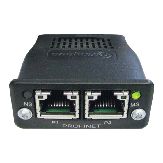
Alle in diesem Dokument beschriebenen Arbeiten und Funktionen dürfen nur von geschultem Fachpersonal ausgeführt werden, wenn folgende Dokumente vollständig gelesen und verstanden wurden: ▶ dieses Dokument ▶ die Bedienungsanleitung des Roboterinterface “RI FB PRO/i“ ▶ sämtliche Bedienungsanleitungen der Systemkomponenten, insbesondere Sicherheitsvorschriften Anschlüsse und Pin-Belegung RJ 45 ProfiNet An-... - Page 5 (1) LED MS - Modulstatus Aus: keine Versorgungsspannung / Modul im Setup- oder Initialisierungs-Mo- Leuchtet grün: normaler Betrieb Blinkt grün (einmal): Diagnoseprozess läuft Leuchtet rot: Ausnahmezustand, schwerer Feh- ler, ... Leuchtet abwechselnd rot und grün: Firmwareupdate. Während des Up- LED MS - Modulstatus dates das Modul nicht von der Span- nungsversorgung trennen - dies könnte Schäden am Modul zur Folge...
-
Page 6: Eigenschaften Der Datenübertragung
Konfigurationsparameter anzugeben, damit das Busmodul mit dem Robo- ter kommunizieren kann. Parameter: Wert: Device ID 0320 (800 ) Fronius ProfiNet 2-Port Vendor ID 01B0 (432 ) Fronius International GmbH Station Type fronius-fb-pro-pn-2p Die folgenden Parameter geben Detailinformationen über das Busmodul. Auf die Daten kann durch den Profibus-Master mittels azyklischer Lese/Schreib- Dienste zugegriffen werden. -
Page 7: Vergabe Der Ip-Adresse Des Busmoduls
Standard-Benutzernamen (admin) und Passwort (admin) eingeben Website der Stromquelle wird angezeigt IP-Adresse des Busmoduls anzeigen: Auf der Website der Stromquelle den Reiter „RI FB PRO/i“ auswählen Bei Punkt „Feldbus Konfiguration“ wird die aktuelle IP-Adresse angezeigt Beispielsweise: 192.168.0.12 IP-Einstellungen Für das Löschen der IP-Einstellungen und des Gerätenamens stehen die zwei... - Page 8 Bei Punkt „Modulkonfiguration / Modul-Operationen“ das Feld „Werksein- stellungen setzen“ auswählen Bei Punkt „Modulkonfiguration / Modul-Operationen“ das „Feldbus-Modul neu starten“ auswählen das Feldbus-Modul wird neu gestartet und die IP-Einstellungen werden gelöscht...
-
Page 9: Prozessdaten-Breite Des Busmoduls Einstellen
Standard-Benutzernamen (admin) und Passwort (admin) eingeben Website der Stromquelle wird angezeigt Prozessdaten-Breite des Busmoduls einstellen: Auf der Website der Stromquelle den Reiter „RI FB PRO/i“ auswählen Bei Punkt „Prozessdaten“ die gewünschte Prozessdaten-Konfiguration auswählen „Speichern“ auswählen Die Feldbus-Verbindung wird neu gestartet und die Konfiguration über-... -
Page 10: Ein- Und Ausgangssignale
Ein- und Ausgangssignale Datentypen Folgende Datentypen werden verwendet: UINT16 (Unsigned Integer) Ganzzahl im Bereich von 0 bis 65535 SINT16 (Signed Integer) Ganzzahl im Bereich von -32768 bis 32767 Umrechnungsbeispiele: für positiven Wert (SINT16) z.B. gewünschter Drahtvorschub x Faktor 12.3 m/min x 100 = 1230 = 04CE für negativen Wert (SINT16) z.B. -
Page 11: Eingangssignale (Vom Roboter Zur Stromquelle)
Eingangssignale (vom Roboter zur Stromquelle) Prozess- Adresse Image relativ absolut Signal Bereich Welding Start steigend Robot ready High Working mode Bit 0 High Siehe Tabelle Working mode Bit 1 High Wertebereich Working mode Bit 2 High Working mode Working mode Bit 3 High auf Seite Working mode Bit 4... - Page 12 Prozess- Adresse Image relativ absolut Signal Bereich Welding Simulation High Synchro pulse on High — — — Booster manual High Wire brake on High Torchbody Xchange High ü ü — Teach mode High — — — Wire sense start steigend Wire sense break steigend —...
- Page 13 Prozess- Adresse Image relativ absolut Signal Bereich — — — — — — — — ExtInput1 => OPT_Output High ExtInput2 => OPT_Output High ü ü ExtInput3 => OPT_Output High ExtInput4 => OPT_Output High ExtInput5 => OPT_Output High ExtInput6 => OPT_Output High ExtInput7 =>...
- Page 14 Prozess- Adresse Image relativ absolut Signal Bereich Beim Schweißverfahren MIG/MAG Puls-Synergic, MIG/MAG Standard-Syn- ergic, -10,0 bis MIG/MAG PMC, SINT16 10,0 MIG/MAG LSC, [Schritte] CMT: Arclength correction Beim Schweißverfahren MIG/MAG Standard-Ma- 0,0 bis 96-111 ü ü nuell: UINT16 6553,5 Welding voltage Beim Job-Betrieb: -10,0 bis SINT16...
-
Page 15: Wertebereich Working Mode
Prozess- Adresse Image relativ absolut Signal Bereich 192-199 200-207 208-215 — ü 216-223 224-231 — ü 232-239 240-247 OFF / 1 bis Wire forward / backward UINT16 65535 ü length 248-255 [mm] 256-263 OFF / 0,5 Wire sense edge detection UINT16 bis 20,0 ü... -
Page 16: Wertebereich Processline Selection
Wertebereich Bit 1 Bit 0 Beschreibung Processline Prozesslinie 1 (default) selection Prozesslinie 2 Prozesslinie 3 Reserviert Wertebereich Prozesslinien-Auswahl Wertebereich Bit 1 Bit 0 Beschreibung TWIN mode TWIN Single mode TWIN Lead mode TWIN Trail mode Reserve Wertebereich TWIN-Betriebsart... -
Page 17: Verfügbarkeit Der Ausgangssignale
Verfügbarkeit Die nachfolgend angeführten Ausgangssignale sind ab Firmware V1.9.2 des RI FB der Ausgangssi- PRO/i verfügbar. gnale Ausgangssignale (von der Strom- quelle zum Ro- boter) Prozess- Adresse Image relativ absolut Signal Bereich Heartbeat Powersource High/Low 1 Hz Power source ready High Warning High... - Page 18 Prozess- Adresse Image relativ absolut Signal Bereich Command value out of High range Correction out of range High — Limitsignal High — — Main supply status — ü ü Sensor status 1 High Siehe Tabelle Sensor status 2 High ordnung Sensorsta- tus 1-4 auf Seite Sensor status 3...
- Page 19 Prozess- Adresse Image relativ absolut Signal Bereich Process Bit 0 High Process Bit 1 High Siehe Tabelle Wer- Process Bit 2 High tebereich Process auf Seite Process Bit 3 High Process Bit 4 High — Touch signal gas nozzle High TWIN synchronization High active...
-
Page 20: Zuordnung Sensorstatus
Prozess- Adresse Image relativ absolut Signal Bereich 160-167 -327,68 Motor current M1 SINT16 bis 327,67 ü 168-175 176-183 -327,68 Motor current M2 SINT16 bis 327,67 ü 184-191 192-199 -327,68 Motor current M3 SINT16 bis 327,67 ü 200-207 208-215 — ü 216-223 224-231 —... -
Page 21: Wertebereich Safety Status
Wertebereich Bit 1 Bit 0 Beschreibung Safety status Reserve Halt Stopp Nicht eingebaut / aktiv Wertebereich Bit 1 Bit 0 Beschreibung Active process Prozessline 1 line Bit Prozessline 2 Prozessline 3 Prozessline 4 Wertebereich Bit 4 Bit 3 Bit 2 Bit 1 Bit 0 Beschreibung... - Page 23 Table of contents General Safety Connections and Indicators Data Transfer Properties System Reactions in the Event of Communication Problems Configuration Parameters Assignment of the Bus Module IP Address Assignment of the Bus Module IP Address Displaying the Bus Module IP Address Deleting IP Settings and Device Names Set the Process Data Width of the Bus Module Setting the process data width of the bus module...
-
Page 24: General
▶ This document ▶ The robot interface Operating Instructions “RI FB PRO/i” ▶ All system component Operating Instructions, especially the safety rules. Connections and Pin assignment RJ45 ProfiNet con-... -
Page 25: Data Transfer Properties
(1) MS LED - module status Off: No supply voltage/module in setup or initialization mode Lights up green: Normal operation Flashes green (once): Diagnosis process is running Lights up red: Exception state, serious fault, etc. Lights up green and red alternately Firmware update. -
Page 26: System Reactions In The Event Of Communication Problems
Parameters Value Device ID 0320 (800 ) Fronius ProfiNet 2-port Vendor ID 01B0 (432 ) Fronius International GmbH Station type fronius-fb-pro-pn-2p The following parameters provide detailed information about the bus module. -
Page 27: Assignment Of The Bus Module Ip Address
The website of the power source is displayed Display IP address of the bus module: On the power source website, select the "RI FB PRO/i" tab The current IP address is displayed under the "Fieldbus configuration" point. For example: 192.168.0.12... - Page 28 Under the "Module configuration/Module operations" point, select the "Set factory settings" field Under the "Module configuration/Module operations" point, select "Restart field-bus module" The field-bus module is restarted and the IP settings are deleted...
-
Page 29: Set The Process Data Width Of The Bus Module
Enter the standard user name (admin) and password (admin) The website of the power source is displayed Set the process data width of the bus module: On the power source website, select the "RI FB PRO/i" tab Under "Process data", select the desired process data configuration Select "Save"... -
Page 30: Input And Output Signals
Input and output signals Data types The following data types are used: UINT16 (Unsigned Integer) Whole number in the range from 0 to 65535 SINT16 (Signed Integer) Whole number in the range from -32768 to 32767 Conversion examples: for a positive value (SINT16) e.g. -
Page 31: Input Signals (From Robot To Power Source)
Input signals (from robot to power source) Process Address image Absolu- Relative Signal Range Increa- Welding Start sing Robot ready High Working mode Bit 0 High Working mode Bit 1 High See table Value Range for Working mode Bit 2 High Working Mode Working mode Bit 3... - Page 32 Process Address image Absolu- Relative Signal Range Welding Simulation High Synchro pulse on High — — — Booster manual High Wire brake on High Torchbody Xchange High — ü ü Teach mode High — — — Increa- Wire sense start sing Increa- Wire sense break...
- Page 33 Process Address image Absolu- Relative Signal Range TWIN mode Bit 0 High See table Value Range for TWIN Mode on page TWIN mode Bit 1 High — — — See table Value Range for Docu- Documentation mode High mentation Mode on page —...
- Page 34 Process Address image Absolu- Relative Signal Range — — — — — — — — ExtInput1 => OPT_Output High ExtInput2 => OPT_Output High ü ü ExtInput3 => OPT_Output High ExtInput4 => OPT_Output High ExtInput5 => OPT_Output High ExtInput6 => OPT_Output High ExtInput7 =>...
- Page 35 Process Address image Absolu- Relative Signal Range For the welding processes MIG/MAG pulse synergic, MIG/MAG standard syner- gic, -10.0 to MIG/MAG PMC, SINT16 10.0 MIG/MAG LSC, [steps] CMT: Arclength correction For the welding process MIG/MAG standard manu- 0.0 to 0–7 96–111 ü...
-
Page 36: Value Range For Working Mode
Process Address image Absolu- Relative Signal Range 176– 0–7 Penetration stabilizer SINT16 0.0 to 10.0 ü 184– 0–7 192– 0–7 200– 0–7 208– 0–7 — ü 0–7 216–223 0–7 224–231 — ü 0–7 232–239 240– 0–7 OFF / 1 to Wire forward / backward UINT16 65535... -
Page 37: Value Range For Documentation Mode
Bit 4 Bit 3 Bit 2 Bit 1 Bit 0 Description Stop coolant pump Value range for operating mode Value Range for Bit 0 Description Documentation Seam number of power source (internal) Mode Seam number of robot (Word 19) Value range for documentation mode Value range Pro- Bit 1 Bit 0... -
Page 38: Availability Of The Output Signals
Availability of The output signals listed below are available from firmware V1.9.2 of the RI FB the output si- PRO/i onwards. gnals Output signals (from power source to robot) Process Address image Absolu- Relative Signal Range Heartbeat Powersource High/Low 1 Hz Power source ready High Warning... - Page 39 Process Address image Absolu- Relative Signal Range Command value out of High range Correction out of range High — Limitsignal High — — Main supply status — ü ü Sensor status 1 High See table Assign- Sensor status 2 High ment of Sensor Sta- tuses 1–4 on page...
- Page 40 Process Address image Absolu- Relative Signal Range Process Bit 0 High Process Bit 1 High See table Value Process Bit 2 High Range for Process on page Process Bit 3 High Process Bit 4 High — Touch signal gas nozzle High TWIN synchronization High...
- Page 41 Process Address image Absolu- Relative Signal Range 144– 0–7 0 to Warning number UINT16 ü 65,535 152– 0–7 160– 0–7 -327.68 to Motor current M1 SINT16 ü 327.67 [A] 168– 0–7 176– 0–7 -327.68 to Motor current M2 SINT16 ü 327.67 [A] 184–...
-
Page 42: Assignment Of Sensor Statuses
Assignment of Signal Description Sensor Statuses Sensor status 1 OPT/i WF R wire end (4,100,869) 1–4 Sensor status 2 OPT/i WF R wire drum (4,100,879) Sensor status 3 OPT/i WF R ring sensor (4,100,878) Sensor status 4 Wire buffer set CMT TPS/i (4,001,763) -
Page 43: Value Range Safety Status
Value range Bit 1 Bit 0 Description Safety status Reserve Hold Stop Not installed / active Value range of Bit 1 Bit 0 Description Active process Process line 1 line Bit Process line 2 Process line 3 Process line 4 Value Range for Bit 4 Bit 3...
Need help?
Do you have a question about the RI FB PRO/i and is the answer not in the manual?
Questions and answers