
Related Manuals for Ropox Verti-Inside


Summary of Contents for Ropox Verti-Inside
- Page 1 QR code to mounting video Ropox Verti-Inside User Manual Mounting Instructions Service Manual Keep this folder with the product at all times! TF 200.0069_uk / Rev 002 / 12-09-2023...
-
Page 2: Table Of Contents
INTRODUCTION ..........................3 CONFORMITY WITH EU DIRECTIVE AND UK DIRECTIVE .............. 3 APPLICATION............................3 TECHNICAL DATA ..........................4 DIMENSION SKETCH OF VERTI-INSIDE ................... 5 Construction see dimensions on the following page ..............5 Cupboard sizes........................... 6 Operation of Verti-Inside ......................8 Wiring diagram ........................... -
Page 3: Introduction
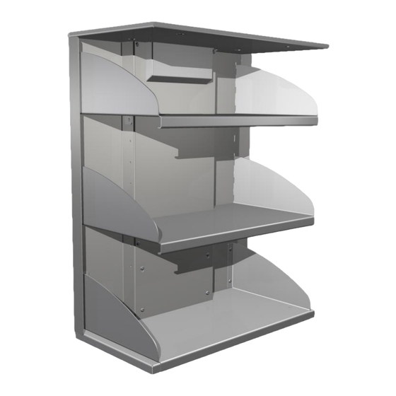
Application Verti-Inside is designed to obtain optimum working height for the user. Verti-Inside is designed to adjust the height of wall cupboards. Verti-Inside must NOT be used as a lifting unit or person lifter. The product must be used indoor, under normal room temperature and humidity conditions as stated in Section 4. -
Page 4: Technical Data
Approx. 33 sec. Travel 495mm / 19.4in Temperature: 5-45° C Air humidity: 5-85% (non-condensing) Complaints: See Complaints page 28 Manufacturer: Ropox A/S, DK-4700 Næstved, Tel.: +45 55 75 05 00 e-mail: info@ropox.dk - www.ropox.dk TF 200.0069_uk / Rev 2 Page 4... -
Page 5: Dimension Sketch Of Verti-Inside
Dimension sketch of Verti-Inside It is important that cables to the control unit are flexible and can move freely within the height adjustment range of the unit. Depth 265mm or 310mm Depth 10.4in or 12.2in 350/450/550/650/750/850/950mm iincrementsval 13.7/17.7/21.6/25.6/29.5/33.4/37.4 in Travel: 495mm/19.4in 495mm/19.4in... -
Page 6: Construction See Dimensions On The Following Page
We recommend the installation of an empty conduit in the wall to accommodate the cable (ø3.5cm). If a high cabinet stands in the immediate vicinity of Verti-Inside, the cable may be run through the cabinet to avoid the conduit in the wall. - Page 7 Cabinet height of 70.4 cm / 27.7 in Cabinet height above 70.4 cm / 27.7in electric installation Fixed shelf for mounting electric the top safety stop installation TF 200.0069_uk / Rev 2 Page 7...
-
Page 8: Operation Of Verti-Inside
Operation of Verti-Inside The height of the cupboard is adjusted by means of the control switch connected to the control unit. The cupboard is adjusted upwards by pressing the UP symbol of the control switch and downwards by pressing the DOWN symbol of the control switch. -
Page 9: Mounting Instructions
Mounting instructions Mounting must always be carried out by competent personnel Before starting installation, check that all parts mentioned in the list of components have been delivered. See list of components, Section 8. / 1in Wall Remove back and bottom from the cupboard. Drill 1 x Ø40mm/1.6in hole in the Note! top of the cupboard for cables... - Page 10 Mount suspension fixture 30-40400-019 on wall When installing the verti-Inside 2.1in in a cabinet height of 704 mm / 27.7 in the safety stop will be 20mm/0,8in lower than the cabinet. 20mm/0.8in Lift lifting unit 30-40400-042 into the cupboard and hook it onto the suspension fixture Drill holes in wall.
- Page 11 1. Connect the control switch to HS If required, use extension cord: 93000162 Pull the cable behind the motor and through the hole at the top of the cupboard 2. Pull mains cable behind the motor and through the hole at the top of the cupboard, connect and turn on power Connect the motor cable 96000814 to M1 Mains cable...
- Page 12 Monting of top safety stop 22mm / 0.8in Wall Connect safety stop to control unit, to Mount upper safety stop on top of the the cable marked: S1. cupboard. (Illustration shows cupboard (See wiring diagram page 8) viewed from below) 4 x Ø5x20 4 x 96121409, wood screw...
- Page 13 Mount cover plate 30-40400-085 The top of the cover plate has The bottom of the cover plate has a flange “keyholes” fitting the pre-mounted fitting around the lifting unit. When the ”keyhole” and flange “catch”, push bolts of the lifting unit the plate upward and tighten the bolts.
- Page 14 Lift front plate into the cupboard and hook it onto the pre-mounted bolts of the lifting unit. Now mount the remaining 6 bolts 6 x M6x10 TF 200.0069_uk / Rev 2 Page 14...
- Page 15 Connect safety stop and spiral cable Mount cable relief for mains cable on wall TF 200.0069_uk / Rev 2 Page 15...
- Page 16 Place control switch acc. to customer’s wish and connect by means of cable: 97000245. If required, use extension cord: 93000162 Mount 97701-841 and 97701-842 shielding for control switch 2 x M3x8 TF 200.0069_uk / Rev 2 Page 16...
-
Page 17: Mounting Of Accessories
6.1.2 Downloading the Ropox Connect App As an option to operate certain Ropox products, it’s possible to download the free Ropox Connect App, which makes it possible to operate the product wirelessly. The Ropox Connect App allows you to operate the product upwards or downwards and has the option of saving height settings, allowing users to easily change from a standing height to a sitting height. -
Page 18: Performance Test
7. Performance test After completed installation and before use all functions of the module must be tested. After that a performance test must be carried out at least once a year by competent personnel. 1. Check that the mounting instructions have been observed. 2. -
Page 19: List Of Components, Verti-Inside
List of components, Verti-Inside Item number Designation Number Illustration 30-40400-453 Verti-InsideElectric 1 (one) Lifting unit 30-40400-019 Suspension fixture 1 (one) 30-40601-144 Relief for mains cable 1 (one) 96000169 Cable clips 24mm/1in 1 (one) 95010416 M4x16 bolt, cylindrical head 2 (two) -
Page 20: Options, Verti-Inside
Control switch with spiral cable 1 (one) Smartbox 30-69002-1: 1 pc. Option for safety stop plate To be ordered if Diagonal is mounted above a FlexiElectric Ropox connect app 30-90591: Remote control with app 1 pc. TF 200.0069_uk / Rev 2 Page 20... - Page 21 Safety stop with LED spot 1W Incl. transformer. Incl. cables For Verti-Inside with depth 26,5cm/10.4in 30-40444 Led for 40cm/15.7in safety stop 30-40445 Led for 50cm/19.7in safety stop 30-40446 Led for 60cm/23.6in safety stop 30-40447 Led for 70cm/27.5in safety stop 2pcs 30-40448 Led for 80cm/31.4in safety stop...
-
Page 22: Placing Of Led Spot
10. Placing of LED spot. 13.2in 17.2in 21.1in 25in 15.7in 19.7in 27.5in 23.6in 10.6in 5.5in 14in 5.5in 8.6in 6.6in 29in 33in 36.9in 31.5in 35.4in 39.4in 5.5in 18in 5.5in 18.7in 21.1in 7.8in 7.8in TF 200.0069_uk / Rev 2 Page 22... -
Page 23: Cables For Led Spot
11. Cables for LED spot. Spiral cable male/female is prepared for mounting of light. For detailed instuctions see the folder that comes with the med LED spot. TF 200.0069_uk / Rev 2 Page 23... -
Page 24: Safety In Use
➢ Verti-Inside is a cupboard module and must not be used as a lifting unit or person lifter. ➢ Always use the unit in a manner eliminating the risk of damage to persons or property. -
Page 25: Cleaning/ Maintenance
Check that all cables have been mounted correctly and are undamaged. After each inspection, complete the service schedule. Only use Ropox original spare parts for replacement. If other spare parts are used, the right to complain may become void. TF 200.0069_uk / Rev 2... -
Page 26: Service Schedule, Operation And Maintenance
4. Check that cables for safety stops are connected to control unit and safety stops. 5. Check that safety stops have not been activated. Reset procedure 6. If none of the above has helped reset the unit: − Remove all weight from Verti-Inside − Disconnect motorcables − Disconnect mains cable and wait 5 sec −... -
Page 27: Label
This manual must be read prior to use. Waste must be sorted – if possible for recycling. Ropox is the manufacturer of the product in question. CE marking. This product meets the requirements for General Safety and Functionality of the current EU Directives and Standards. -
Page 28: Complaints
Complaints See General Terms of Sale and Delivery on www.ropox.dk Keep this folder with the product at all times! ROPOX A/S Ringstedgade 221 DK – 4700 Næstved Tel.: +45 55 75 05 00 E-mail: info@ropox.dk www.ropox.dk TF 200.0069_uk / Rev 2...
Need help?
Do you have a question about the Verti-Inside and is the answer not in the manual?
Questions and answers