
Related Manuals for Ropox KitFrame Flexi


Summary of Contents for Ropox KitFrame Flexi
- Page 1 FlexiManual, 30-65XXX-8, 3 legs User Manual Mounting Instructions Keep this folder with product at all times! PDF 6021 / 01.08.2009 PA 2004 00634...
-
Page 2: Table Of Contents
PERFORMANCE TEST ............................ 20 Performance test, manually operated frame ....................20 Performance test, electrically operated frame .................... 20 LIST OF COMPONENTS FOR KITFRAME FLEXI FOR WORKTOP 60-300 CM ......... 21 SAFETY IN USE ..............................24 CLEANING AND MAINTENANCE ........................ 25 11.1 Cleaning .............................. -
Page 3: Introduction
Introduction You have chosen Flexi, the multi-flexible, height-adjustable, easy-to-mount frame. The frame may be used separately or in combination with Diagonal or Verti, the adjustable system for wall cupboards. The frame has no inconvenient fascia and, consequently, the adjustment of the working height from 65 to 95 cm + worktop thickness may be fully utilised. -
Page 4: Technical Data Kitframe Flexi
Max. 10 % conform to 1 min. active / 9 min. pause Speed: Approx. 12 Lifting time stroke 30 cm: Approx. 30 sec. Temperature: 5-45° C Air humidity: 5-85% (non-condensing) Complaints: See complaints, page 28. Manufacturer: Ropox A/S, DK-4700 Naestved, Tel.: +45 55 75 05 00 Page 4... -
Page 5: Supply Points, Water Supply And Waste
Supply points, water supply and waste Length of the worktop Length of the worktop Length of Aluminium bar = Length of worktop minus 5 cm Length of Hex 6 shaft = Length of worktop minus 15 cm It is advisable to place water supply and waste within the hatched area. Also it is important to use flexible hoses for water supply and waste to ensure that the Flexi will move freely without obstacles within the height adjustment range 65-95 cm. -
Page 6: Tips Og Tricks
Tips og tricks 5.1.1 Tension in upper bolts of Flexi frames Calculation has been done for ONE leg, which will be worst case. Worktop 62 cm deep. Max. Permissible load at the Flexi frame is 150 Kg, evenly distributed. In this example we have put the max. 62 cm 150 Kg Load in the front of the worktop. -
Page 7: Mounting Instructions, Illustrations
Mounting instructions, illustrations The equipment should always be assembled by competent personnel. Prior to assembly check that all parts have been provided. See list of components, from page 21. See also mounting instructions page 14 to 20. 6.1.1 6.1.2 6.1.3 2,5 cm 6.1.5 6.1.4... - Page 8 8 cm 6.3.3 6.4.1 6.4.2 6.5.1 2,5 cm 6.5.2 6.5.3 6.6.1 6.6.2 Page 8...
- Page 9 6.8.1 6.7.1 6.9.1 6.8.2 6.9.3 6.9.2 6.9.5 6.9.4 Page 9...
- Page 10 6.10.1 6.10.2 6.11.1 6.11.2 L= Worktop length 6.12.1 6.12.2 L= Worktop length L= Worktop length Lower concealment panel Lower cover concealment panel in case of supporting feet 8 cm 8 cm Distance between feet 6.12.3 6.12.4 Page 10...
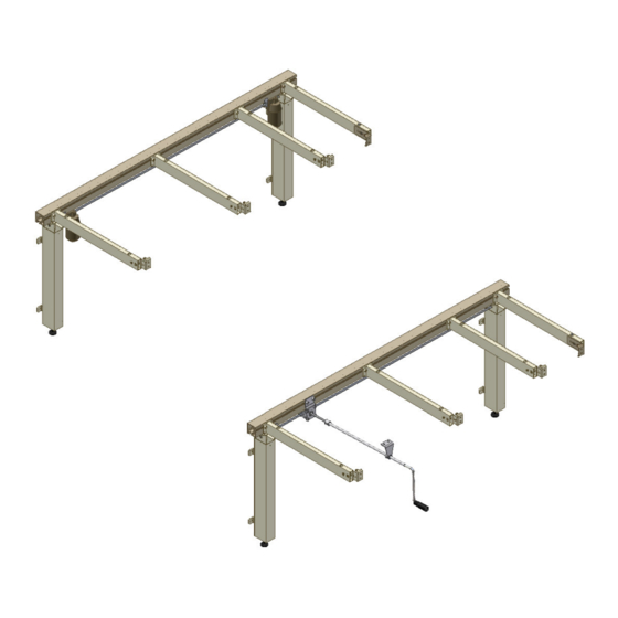
- Page 11 Mounting instructions, illustrations converting into electrical 6.13.1 6.13.2 6.13.3 6.13.4 6.13.5 6.13.6 21,5 cm 18,5 Placement of waste pipe 6.13.7 6.14.1 Page 11...
- Page 12 Mounting instructions, illustrations converting into electrical Control Box must be mounted on Underside of worktop Mains cable Safety stop connection See 6.13.1 & 6.13.2 Motor cable M1 Cable for control switch Motor cable M2 6.15.1 Control Box 6.15.2 6.15.3 Safety strip Ø18 6.16.1 6.17.1...
- Page 13 Mounting instructions, accessories 6.18.2 6.18.1 6.19.1 6.18.3 Page 13...
-
Page 14: Mounting Instructions, Descriptions
Mounting instructions, descriptions The equipment should always be assembled by competent personnel. Prior to assembly check that all parts have been provided. See list of components, from page 21. See also mounting drawings from page 7. Assembly of frame 6.1.1 Place the aluminium profile on the floor. If supporting feet have been ordered, first see mounting of feet, item 6.15. -
Page 15: Mounting The Frame On The Wall
Mounting the frame on the wall 6.3.1 Place the frame against the wall and align it. Adjust the two threaded bolts under the legs to ensure that the frame is horizontal. 6.3.2 To obtain the correct height (65-95 cm without worktop) adjust the threaded bolt to each leg. -
Page 16: Adjusting The Worktop/ Support Arms
Adjusting the worktop/ support arms 6.8.1 After placing the worktop on the frame you may have to compensate for the weight of the worktop if the frame is no longer horizontal from the wall to the front fascia. 6.8.2 By means of the two lower screws of each support arm the ”tilting” may be adjusted. Start by loosening the two screws fastening the support arm to the aluminium profile and adjust the two lower screws to make the worktop horizontal. -
Page 17: Mounting The Concealment Panels
6.12 Mounting the concealment panels Option: Fittings for mounting the concealment panels (panels not supplied by Ropox) For three-legged frames use two sets of fittings. 6.12.1 Inside/lower concealment panels: Fasten the Z-fittings to the wall in the middle between the legs. Fit Velcro on the Z-fittings and the concealment panels. -
Page 18: Mounting The Flexible Water Connections And Waste Hoses
6.14 Mounting the flexible water connections and waste hoses Arrange for the fixed feed pipes on the wall to be pointing down, at a height of max. 30 cm. This will ensure that the flexible feed pipes will always flex in a neat curve close to the wall without kinking. -
Page 19: Mounting The Safety Strip Under The Worktop
6.17 Mounting the safety strip under the worktop Option: Ropox always recommends the use of safety strips for electrically operated frames. Be careful not to bend or damage the safety strip during transport or mounting. Be careful when mounting the safety strip, bending or twisting can reflect on the performance of the safety strip. -
Page 20: Performance Test
Performance test Performance test, manually operated frame After installation and prior to use all functions of Flexi must be tested. The test must be carried out by competent personnel. Subsequently the test shall be carried out at least once a year: 1. -
Page 21: List Of Components For Kitframe Flexi For Worktop 60-300 Cm
List of components for KitFrame Flexi for worktop 60-300 cm Legs, standard height 65-95 cm. 30-67600: Length of worktop = 60-204 cm 2 legs Length of worktop = 205-300 cm 3 legs The legs comprise: 30-67681 Spacers (0.15 cm) 3 pcs./leg... - Page 22 Options for KitFrame Flexi Support arm for worktop depth 70-72 cm 30-67621: Length of worktop = 60-104 cm 2 pcs. Length of worktop = 105-204 cm 4 pcs. Length of worktop = 205-254 cm 5 pcs. Length of worktop = 255-300 cm 7 pcs.
- Page 23 Electrical kit 1 for Flexi 60-104 cm 30-67866: 1 pc. 30-67801: Motor (16x8x8 cm): Motor vertical 1 pc. Incl. motor cable (200 cm) and fitting 30-67851: Control unit, Slow speed(22x11x7 cm): 1 set for 1 motor 240VAC Incl. mains cable (300 cm) The control unit comprises: 98002014 Y-cable 1 pc.
-
Page 24: Safety In Use
If the Flexi frame has not been installed in accordance with these mounting instructions, the guarantee may become void. Only use Ropox original spare parts as replacement parts. If other spare parts are used, the guarantee may become void. Page 24... -
Page 25: Cleaning And Maintenance
Check that all cables have been fitted correctly and are undamaged. After each inspection the service schedule shall be filled in. See item 11.3. Only use Ropox original spare parts as replacement parts. If other parts are used, the guarantee may become void. -
Page 26: Service Schedule, Operation And Maintenance
11.3 Service schedule, operation and maintenance Service and maintenance Service and maintenance Serial No.: Serial No.: Date: Date: Sign: Sign: Remarks: Remarks: Service and maintenance Service and maintenance Serial No.: Serial No.: Date: Date: Sign: Sign: Remarks: Remarks: Trouble shooting 12.1 Manuel operated frames a) The frame seems loose or unstable The screws assembling the frame have not been securely tightened. -
Page 27: Ce-Marking
CE-marking Manually adjustable frames: Flexi, manual with 2 legs 60 – 204 cm Flexi, manual with 3 legs 205 – 300 cm Electrically adjustable frames: Flexi, electrical with 1 motor and 2 legs 60 – 104 cm Flexi, electrical with 2 motors and 2 legs 105 –... -
Page 28: Guarantee
Complaints We refer to our general Terms of sale and delivery on our homepage www.ropox.com ROPOX A/S Ringstedgade 221 DK – 4700 Naestved Tel.: +45 55 75 05 00 Fax.: +45 55 75 05 50 E-mail: info@ropox.dk www.ropox.com Page 28...
Need help?
Do you have a question about the KitFrame Flexi and is the answer not in the manual?
Questions and answers