Advertisement
Quick Links
www.ti.com
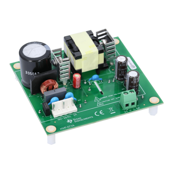
EVM User's Guide: UCC28750EVM-071 UCC287502
Using the UCC28750EVM-071 60-W AC to DC Converter
Description
The UCC28750EVM-071 is a 60-W evaluation module
(EVM) for evaluating an off-line power AC to
DC flyback converter. The UCC28750EVM-071 is
intended for evaluation purposes and is not intended
to be an end product. The UCC28750EVM-071
converters 85-V
to 265-V
RMS
to 24-V
, capable of delivering 60 W of output
DC
power. This evaluation module uses the UCC287502
Constant-Voltage Flyback Controller Using Opto-
Coupled Feed-Back in a 60 W converter to provide
2.5 A of constant charge current. The input accepts
a voltge range of 85 VAC to 265 VAC. Depending
upon the operating conditions, the control law
algorithm modulates the switching frequency or the
peak primary current to satisfy the power transfer
requirements. The programmable slope compensation
enables both CCM and DCM operation. Power-boost
mode provides additional power for momentary peak
demand.
SLUUCW5 – NOVEMBER 2023
Submit Document Feedback
input voltage down
RMS
UCC28750EVM-071
Copyright © 2023 Texas Instruments Incorporated
Get Started
1. Read and study this user's guide completely
before evaluating
2. Order the
UCC28750EVM-071
step 1 and 2 is met
3. Setup and test the UCC28750EVM-071 per user's
guide instructions
Features
•
Regulated 24 V ,+/-5%, 60 W Ouput
•
Wide Input Range 85 to 265-V RMS
•
Max Load Efficency > 90%
Applications
•
Isolated offline AC/DC power supply
•
Industrial AC/DC
for grid infrastructure, appliances
•
Audio, printer, TV, set-top box offline AC/DC
•
Battery charger
•
Merchant DIN rail power
•
Electricity meter
•
String
inverter,
Micro inverter
•
Small home
appliances,
indoor/outdoor unit
Using the UCC28750EVM-071 60-W AC to DC Converter
Description
for evaluation if
supply,
Server PSU
Major
appliances, AC
1
Advertisement

Related Manuals for Texas Instruments UCC28750EVM-071


Summary of Contents for Texas Instruments UCC28750EVM-071
- Page 1 Description EVM User's Guide: UCC28750EVM-071 UCC287502 Using the UCC28750EVM-071 60-W AC to DC Converter Description Get Started The UCC28750EVM-071 is a 60-W evaluation module 1. Read and study this user's guide completely (EVM) for evaluating an off-line power AC to before evaluating DC flyback converter.
-
Page 2: Kit Contents
1 Evaluation Module Overview 1.1 Introduction The UCC28750EVM-071 has frequency foldback and burst mode enable higher efficiency and standby performance at light load. Opto-coupled feed-back maintains a tightly regulated output with fast dynamic response to load transients. The controller further enhances the efficient operation with valley switching. The UCC287502 also includes a omprehensive protection features including UVLO/OVLO, OTP, OPP, OVP, OCP, brown-out detection, and options to latch and auto-restart. - Page 3 Output Load: Resistive or electronic load capable handling 60 W at 24 V. Recommended Wire Gauge: Insulated 22 AWG. SLUUCW5 – NOVEMBER 2023 Using the UCC28750EVM-071 60-W AC to DC Converter Submit Document Feedback Copyright © 2023 Texas Instruments Incorporated...
-
Page 4: Test Setup Diagram
CAUTION This EVM has components that reach tempataures of greater than 55℃. Caution must be taken when evaluating the EVM. Using the UCC28750EVM-071 60-W AC to DC Converter SLUUCW5 – NOVEMBER 2023 Submit Document Feedback Copyright © 2023 Texas Instruments Incorporated... - Page 5 Hardware 2.3.1 General Texas Instruments High Voltage Evaluation (TI HV EVM) User Safety Guidelines WARNING Always follow TI’s setup and application instructions, including use of all interface components within the recommended electrical rated voltage and power limits. Always use electrical safety precautions to help verify your personal safety and those working around you.
- Page 6 43.418 39.548 91.08 24.121 1.8872 45.51 49.95 91.11 24.118 2.23 53.83 91.23 24.115 2.7287 72.33 65.813 90.99 0.151 24.32 Using the UCC28750EVM-071 60-W AC to DC Converter SLUUCW5 – NOVEMBER 2023 Submit Document Feedback Copyright © 2023 Texas Instruments Incorporated...
- Page 7 The inductor L1, which is mounted on the PCB and shown in BOM needs to be removed and shorted out to get best efficiency results. Standby Power AC Input Voltage (Volts) Power (mW) SLUUCW5 – NOVEMBER 2023 Using the UCC28750EVM-071 60-W AC to DC Converter Submit Document Feedback Copyright © 2023 Texas Instruments Incorporated...
- Page 8 Load Figure 3-6. Start-up Waveforms at 230Vac and No Figure 3-7. Start-up Waveforms at 230Vac and Full Load Load Using the UCC28750EVM-071 60-W AC to DC Converter SLUUCW5 – NOVEMBER 2023 Submit Document Feedback Copyright © 2023 Texas Instruments Incorporated...
- Page 9 Figure 3-11. Load Transients at 115Vac = 230 VAC = 265 VAC Figure 3-12. Load Transients at 230Vac Figure 3-13. Load Transients at 265Vac SLUUCW5 – NOVEMBER 2023 Using the UCC28750EVM-071 60-W AC to DC Converter Submit Document Feedback Copyright © 2023 Texas Instruments Incorporated...
- Page 10 LOAD Figure 3-14. Voltage Ripple at 85Vac and Full Load Figure 3-15. Voltage Ripple at 265Vac and Full Load Using the UCC28750EVM-071 60-W AC to DC Converter SLUUCW5 – NOVEMBER 2023 Submit Document Feedback Copyright © 2023 Texas Instruments Incorporated...
- Page 11 , CH4 = V GATE Figure 3-16. Steady State Waveform at 85Vac Figure 3-17. Steady State Waveform at 85Vac SLUUCW5 – NOVEMBER 2023 Using the UCC28750EVM-071 60-W AC to DC Converter Submit Document Feedback Copyright © 2023 Texas Instruments Incorporated...
- Page 12 No designated component value means the device is not populated Do not populate (DNP) R20, R7 & C25 (V ariant - 001) Primary_GND Primary_GND Figure 4-1. UCC28750EVM-071 Schematic Using the UCC28750EVM-071 60-W AC to DC Converter SLUUCW5 – NOVEMBER 2023 Submit Document Feedback Copyright © 2023 Texas Instruments Incorporated...
- Page 13 Hardware Design Files 4.2 EVM Assembly and Layout Figure 4-2. EVM Assembly (Top View) SLUUCW5 – NOVEMBER 2023 Using the UCC28750EVM-071 60-W AC to DC Converter Submit Document Feedback Copyright © 2023 Texas Instruments Incorporated...
- Page 14 Hardware Design Files www.ti.com Figure 4-3. EVM Assembly/Layout (Bottom View) Using the UCC28750EVM-071 60-W AC to DC Converter SLUUCW5 – NOVEMBER 2023 Submit Document Feedback Copyright © 2023 Texas Instruments Incorporated...
-
Page 15: Bill Of Materials
MOSFET, N-CH, 700 V, 13 A, TO-220AB IPP65R190C7 Infineon Technologies RES, 511 k, 1%, 0.125 W, AEC-Q200 Grade 0, 0805 ERJ-6ENF5113V Panasonic SLUUCW5 – NOVEMBER 2023 Using the UCC28750EVM-071 60-W AC to DC Converter Submit Document Feedback Copyright © 2023 Texas Instruments Incorporated... -
Page 16: Additional Information
Regulated (SSR) Current-Mode Offline Flyback Controller 5 Additional Information 5.1 Trademarks All trademarks are the property of their respective owners. Using the UCC28750EVM-071 60-W AC to DC Converter SLUUCW5 – NOVEMBER 2023 Submit Document Feedback Copyright © 2023 Texas Instruments Incorporated... - Page 17 STANDARD TERMS FOR EVALUATION MODULES Delivery: TI delivers TI evaluation boards, kits, or modules, including any accompanying demonstration software, components, and/or documentation which may be provided together or separately (collectively, an “EVM” or “EVMs”) to the User (“User”) in accordance with the terms set forth herein.
- Page 18 www.ti.com Regulatory Notices: 3.1 United States 3.1.1 Notice applicable to EVMs not FCC-Approved: FCC NOTICE: This kit is designed to allow product developers to evaluate electronic components, circuitry, or software associated with the kit to determine whether to incorporate such items in a finished product and software developers to write software applications for use with the end product.
- Page 19 www.ti.com Concernant les EVMs avec antennes détachables Conformément à la réglementation d'Industrie Canada, le présent émetteur radio peut fonctionner avec une antenne d'un type et d'un gain maximal (ou inférieur) approuvé pour l'émetteur par Industrie Canada. Dans le but de réduire les risques de brouillage radioélectrique à...
- Page 20 www.ti.com EVM Use Restrictions and Warnings: 4.1 EVMS ARE NOT FOR USE IN FUNCTIONAL SAFETY AND/OR SAFETY CRITICAL EVALUATIONS, INCLUDING BUT NOT LIMITED TO EVALUATIONS OF LIFE SUPPORT APPLICATIONS. 4.2 User must read and apply the user guide and other available documentation provided by TI regarding the EVM prior to handling or using the EVM, including without limitation any warning or restriction notices.
- Page 21 Notwithstanding the foregoing, any judgment may be enforced in any United States or foreign court, and TI may seek injunctive relief in any United States or foreign court. Mailing Address: Texas Instruments, Post Office Box 655303, Dallas, Texas 75265 Copyright © 2023, Texas Instruments Incorporated...
- Page 22 TI products. TI’s provision of these resources does not expand or otherwise alter TI’s applicable warranties or warranty disclaimers for TI products. TI objects to and rejects any additional or different terms you may have proposed. IMPORTANT NOTICE Mailing Address: Texas Instruments, Post Office Box 655303, Dallas, Texas 75265 Copyright © 2023, Texas Instruments Incorporated...
Need help?
Do you have a question about the UCC28750EVM-071 and is the answer not in the manual?
Questions and answers