
Related Manuals for Texas Instruments UCC28742EVM-001


Summary of Contents for Texas Instruments UCC28742EVM-001
- Page 1 Using the UCC28742EVM-001 10-W Converter User's Guide Literature Number: SLUUBU4B March 2018 – Revised June 2018...
- Page 2 Any other use and/or application are strictly prohibited by Texas Instruments. If you are not suitable qualified, you should immediately stop from further use of the HV EVM.
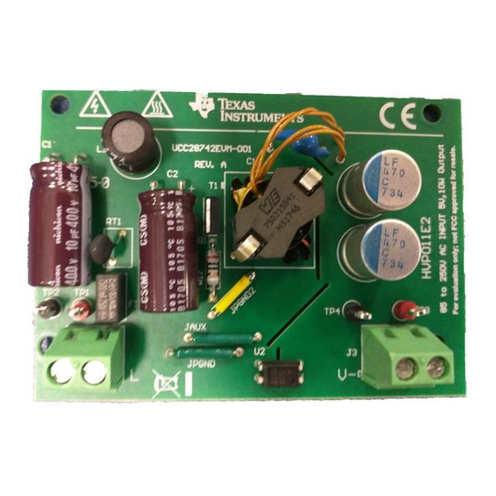
- Page 3 The UCC28742EVM-001 is a 10-W evaluation module for evaluating an off-line power converter applications. The EVM meets CoC tier 2 and DoE Level 6 efficiency and standby power requirements. It is intended for evaluation purposes and is not intended to be an end product. The UCC28742EVM-001 converters 85-V...
-
Page 4: Electrical Performance Specifications
Electrical Performance Specifications www.ti.com Electrical Performance Specifications Table 1. UCC28742EVM-001 Electrical Performance Specifications PARAMETER TEST CONDITIONS UNIT INPUT CHARACTERISTICS Input voltage (RMS) 115/230 Line frequency 50/60 LINE No load input power = 115 V / 230 V RMS, I = 0 A... - Page 5 Schematic www.ti.com Schematic Figure 2. UCC28742EVM-001 Schematic SLUUBU4B – March 2018 – Revised June 2018 Using the UCC28742EVM-001 10-W Converter Submit Documentation Feedback Copyright © 2018, Texas Instruments Incorporated...
-
Page 6: Test Setup Diagram
AC Neutral Source VOUT - 100nF Load 1 ohm Precision Shunt Oscilloscope Figure 3. UCC28742EVM-001 Test Setup Diagram Using the UCC28742EVM-001 10-W Converter SLUUBU4B – March 2018 – Revised June 2018 Submit Documentation Feedback Copyright © 2018, Texas Instruments Incorporated... -
Page 7: Test Points
230 V RMS 10% 20% 30% 40% 50% 60% 70% 80% 90% 100% Output Power D001 D001 Figure 4. Efficiency SLUUBU4B – March 2018 – Revised June 2018 Using the UCC28742EVM-001 10-W Converter Submit Documentation Feedback Copyright © 2018, Texas Instruments Incorporated... - Page 8 Figure 8. = 230V RMS = 230V RMS = Unloaded = 2.5 Ohm LOAD LOAD Figure 9. Figure 10. Using the UCC28742EVM-001 10-W Converter SLUUBU4B – March 2018 – Revised June 2018 Submit Documentation Feedback Copyright © 2018, Texas Instruments Incorporated...
-
Page 9: Load Transients
= 115V RMS = 85V RMS Figure 13. Figure 14. = 230V RMS = 265V RMS Figure 15. Figure 16. SLUUBU4B – March 2018 – Revised June 2018 Using the UCC28742EVM-001 10-W Converter Submit Documentation Feedback Copyright © 2018, Texas Instruments Incorporated... - Page 10 = 2 A Q1 Drain Voltage Evaluation 100 X Probe Q1d, = 265V RMS Figure 19. I = 2A Using the UCC28742EVM-001 10-W Converter SLUUBU4B – March 2018 – Revised June 2018 Submit Documentation Feedback Copyright © 2018, Texas Instruments Incorporated...
-
Page 11: Conducted Emi
NOTE: Please note this was evaluated on an unqualified EMI station. It is recommended that all final designs be verified by agency qualified EMI test house. SLUUBU4B – March 2018 – Revised June 2018 Using the UCC28742EVM-001 10-W Converter Submit Documentation Feedback Copyright © 2018, Texas Instruments Incorporated... - Page 12 Turns ratio (1 – 6):(5 – 3) 5.78:1, ±1% Turns ratio (1 – 2):(2 – 6) 1:1, ±1% Using the UCC28742EVM-001 10-W Converter SLUUBU4B – March 2018 – Revised June 2018 Submit Documentation Feedback Copyright © 2018, Texas Instruments Incorporated...
- Page 13 Np/2 = 26 Turns, 34 AWG, Single Layer Clockwise Bobbin Surface Transformer Inner Core Start Winding Finish Winding Figure 23. Transformer Winding Structure SLUUBU4B – March 2018 – Revised June 2018 Using the UCC28742EVM-001 10-W Converter Submit Documentation Feedback Copyright © 2018, Texas Instruments Incorporated...
- Page 14 EVM Assembly and Layout www.ti.com EVM Assembly and Layout Figure 24. EVM Assembly (Top View) Figure 25. EVM Assembly/Layout (Bottom View) Using the UCC28742EVM-001 10-W Converter SLUUBU4B – March 2018 – Revised June 2018 Submit Documentation Feedback Copyright © 2018, Texas Instruments Incorporated...
-
Page 15: List Of Materials
List of Materials www.ti.com List of Materials UCC28742EVM-001 list of materials as shown in Figure Table 5. UCC28742EVM-001 List of Materials DESCRIPTION PART NUMBER MANUFACTURER C1, C2 Capacitor, aluminum, 10 µF, 400 V, ±20%, TH UCS2G100MPD1TD Nichicon Capacitor, ceramic, 470 pF, 630 V, ±5%, U2J, 1206... -
Page 16: Revision History
Revision History www.ti.com Table 5. UCC28742EVM-001 List of Materials (continued) DESCRIPTION PART NUMBER MANUFACTURER R28, R29 Resistor, 42.2 kΩ, ±1%, 0.1 W, 0603 CRCW060342K2FKEA Vishay-Dale Resistor, 0 Ω, 1%, 0.1 W, AEC-Q200 Grade 0, 0603 RMCF0603ZT0R00 Stackpole Electronics RHVJ Resistor, 0 Ω, 5%, 0.125 W, 0805... - Page 17 STANDARD TERMS FOR EVALUATION MODULES Delivery: TI delivers TI evaluation boards, kits, or modules, including any accompanying demonstration software, components, and/or documentation which may be provided together or separately (collectively, an “EVM” or “EVMs”) to the User (“User”) in accordance with the terms set forth herein.
- Page 18 FCC Interference Statement for Class B EVM devices NOTE: This equipment has been tested and found to comply with the limits for a Class B digital device, pursuant to part 15 of the FCC Rules. These limits are designed to provide reasonable protection against harmful interference in a residential installation.
- Page 19 【無線電波を送信する製品の開発キットをお使いになる際の注意事項】 開発キットの中には技術基準適合証明を受けて いないものがあります。 技術適合証明を受けていないもののご使用に際しては、電波法遵守のため、以下のいずれかの 措置を取っていただく必要がありますのでご注意ください。 1. 電波法施行規則第6条第1項第1号に基づく平成18年3月28日総務省告示第173号で定められた電波暗室等の試験設備でご使用 いただく。 2. 実験局の免許を取得後ご使用いただく。 3. 技術基準適合証明を取得後ご使用いただく。 なお、本製品は、上記の「ご使用にあたっての注意」を譲渡先、移転先に通知しない限り、譲渡、移転できないものとします。 上記を遵守頂けない場合は、電波法の罰則が適用される可能性があることをご留意ください。 日本テキサス・イ ンスツルメンツ株式会社 東京都新宿区西新宿6丁目24番1号 西新宿三井ビル 3.3.3 Notice for EVMs for Power Line Communication: Please see http://www.tij.co.jp/lsds/ti_ja/general/eStore/notice_02.page 電力線搬送波通信についての開発キットをお使いになる際の注意事項については、次のところをご覧ください。http:/ /www.tij.co.jp/lsds/ti_ja/general/eStore/notice_02.page 3.4 European Union 3.4.1 For EVMs subject to EU Directive 2014/30/EU (Electromagnetic Compatibility Directive): This is a class A product intended for use in environments other than domestic environments that are connected to a low-voltage power-supply network that supplies buildings used for domestic purposes.
- Page 20 Notwithstanding the foregoing, any judgment may be enforced in any United States or foreign court, and TI may seek injunctive relief in any United States or foreign court. Mailing Address: Texas Instruments, Post Office Box 655303, Dallas, Texas 75265 Copyright © 2018, Texas Instruments Incorporated...
- Page 21 IMPORTANT NOTICE FOR TI DESIGN INFORMATION AND RESOURCES Texas Instruments Incorporated (‘TI”) technical, application or other design advice, services or information, including, but not limited to, reference designs and materials relating to evaluation modules, (collectively, “TI Resources”) are intended to assist designers who are developing applications that incorporate TI products;...
Need help?
Do you have a question about the UCC28742EVM-001 and is the answer not in the manual?
Questions and answers