Table of Contents
Advertisement
Quick Links
www.ti.com
User's Guide
Using the UCC28782EVM-030 65-W USB-C PD High-
Density Active-Clamp Flyback Converter
SLUUBZ3B – MAY 2020 – REVISED AUGUST 2020
Submit Document Feedback
Using the UCC28782EVM-030 65-W USB-C PD High-Density Active-Clamp
Copyright © 2022 Texas Instruments Incorporated
1
Flyback Converter
Advertisement
Table of Contents

Related Manuals for Texas Instruments UCC28782EVM-030


Summary of Contents for Texas Instruments UCC28782EVM-030
- Page 1 User’s Guide Using the UCC28782EVM-030 65-W USB-C PD High- Density Active-Clamp Flyback Converter SLUUBZ3B – MAY 2020 – REVISED AUGUST 2020 Using the UCC28782EVM-030 65-W USB-C PD High-Density Active-Clamp Submit Document Feedback Flyback Converter Copyright © 2022 Texas Instruments Incorporated...
-
Page 2: Table Of Contents
1 Using the UCC28782EVM-030 65-W USB-C PD High-Density Active-Clamp Flyback Converter Table of Contents 1 Using the UCC28782EVM-030 65-W USB-C PD High-Density Active-Clamp Flyback Converter........2 General Texas Instruments High Voltage Evaluation (TI HV EVM) User Safety Guidelines..........3 Description....................................4 Electrical Performance Specifications..........................5 Schematic Diagram................................ -
Page 3: Using The Ucc28782Evm-030 65-W Usb-C Pd High-Density Active-Clamp Flyback
General Texas Instruments High Voltage Evaluation (TI HV EVM) User Safety Guidelines 2 General Texas Instruments High Voltage Evaluation (TI HV EVM) User Safety Guidelines WARNING Always follow TI’s setup and application instructions, including use of all interface components within their recommended electrical rated voltage and power limits. -
Page 4: Description
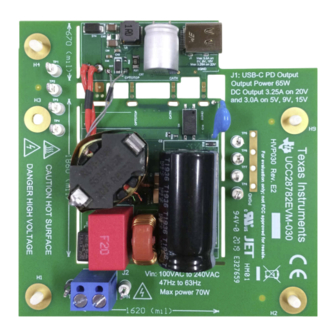
3 Description The UCC28782EVM-030 is a 65-W USB-C PD evaluation module (EVM) for evaluating an off-line active-clamp flyback adapter for notebook charging and other applications. The EVM meets CoC Tier 2 and DoE Level 6 efficiency requirements. It is intended for evaluation purposes and is not intended to be an end product. - Page 5 Description Figure 3-2. UCC28782EVM-030 bottom View Figure 3-3. High-Density Configuration SLUUBZ3B – MAY 2020 – REVISED AUGUST 2020 Using the UCC28782EVM-030 65-W USB-C PD High-Density Active-Clamp Submit Document Feedback Flyback Converter Copyright © 2022 Texas Instruments Incorporated...
-
Page 6: Electrical Performance Specifications
= 100%, 75%, 50% and 25% of rated full-load current for each respective output voltage. The performance listed in this table is achieved using secondary resonance and based on the test results from a single board. Using the UCC28782EVM-030 65-W USB-C PD High-Density Active-Clamp SLUUBZ3B – MAY 2020 – REVISED AUGUST 2020... -
Page 7: Schematic Diagram
Schematic Diagram 5 Schematic Diagram Figure 5-1. UCC28782EVM-030 Schematic Diagram (1 of 2) SLUUBZ3B – MAY 2020 – REVISED AUGUST 2020 Using the UCC28782EVM-030 65-W USB-C PD High-Density Active-Clamp Submit Document Feedback Flyback Converter Copyright © 2022 Texas Instruments Incorporated... - Page 8 Schematic Diagram www.ti.com Figure 5-2. UCC28782EVM-030 Schematic Diagram (2 of 2) Using the UCC28782EVM-030 65-W USB-C PD High-Density Active-Clamp SLUUBZ3B – MAY 2020 – REVISED AUGUST 2020 Flyback Converter Submit Document Feedback Copyright © 2022 Texas Instruments Incorporated...
-
Page 9: Description
6.2 Using the EVM on a Load with USB-C PD Communication UCC28782EVM-030 comes populated with USB-C PD controller (WT6636F) and requires external connection through an on-board USB-C connector to a USB-C PD load so to adjust the board output to obtain 5-V, 9-V, 15-V or 20-V. -
Page 10: Test Setup
Caution: Do not leave EVM powered when unattended. !! Do not apply DC voltage source to this board or damage may happen !! (See above setup of Voltage Source) Using the UCC28782EVM-030 65-W USB-C PD High-Density Active-Clamp SLUUBZ3B – MAY 2020 – REVISED AUGUST 2020 Flyback Converter Submit Document Feedback Copyright ©... -
Page 11: Test Setup Diagram
TP5, TP6, TP7, TP8 Floating, need to solder connections, leave them floating if not used SLUUBZ3B – MAY 2020 – REVISED AUGUST 2020 Using the UCC28782EVM-030 65-W USB-C PD High-Density Active-Clamp Submit Document Feedback Flyback Converter Copyright © 2022 Texas Instruments Incorporated... -
Page 12: Performance Data And Typical Characteristic Curves
20.000 0.325 81.47% CoC Tier 2, 4pt-average 89.0% CoC Tier 2, 10%-load 79.0% Using the UCC28782EVM-030 65-W USB-C PD High-Density Active-Clamp SLUUBZ3B – MAY 2020 – REVISED AUGUST 2020 Flyback Converter Submit Document Feedback Copyright © 2022 Texas Instruments Incorporated... -
Page 13: Efficiency Result Of 4-Point Average At 15-Vout
15.010 0.300 81.10% CoC Tier 2, 4pt-average 88.9% CoC Tier 2, 10%-load 78.9% SLUUBZ3B – MAY 2020 – REVISED AUGUST 2020 Using the UCC28782EVM-030 65-W USB-C PD High-Density Active-Clamp Submit Document Feedback Flyback Converter Copyright © 2022 Texas Instruments Incorporated... -
Page 14: Efficiency Result Of 4-Point Average At 9-Vout
8.981 0.300 79.45% CoC Tier 2, 4pt-average 87.3% CoC Tier 2, 10%-load 77.3% Using the UCC28782EVM-030 65-W USB-C PD High-Density Active-Clamp SLUUBZ3B – MAY 2020 – REVISED AUGUST 2020 Flyback Converter Submit Document Feedback Copyright © 2022 Texas Instruments Incorporated... -
Page 15: Efficiency Result Of 4-Point Average At 5-Vout
4.948 0.300 74.11% CoC Tier 2, 4pt-average 81.8% CoC Tier 2, 10%-load 72.5% SLUUBZ3B – MAY 2020 – REVISED AUGUST 2020 Using the UCC28782EVM-030 65-W USB-C PD High-Density Active-Clamp Submit Document Feedback Flyback Converter Copyright © 2022 Texas Instruments Incorporated... -
Page 16: Efficiency Typical Results
Figure 8-5. V at Full-Load vs. Input Voltge Figure 8-6. V vs. Output Current Using the UCC28782EVM-030 65-W USB-C PD High-Density Active-Clamp SLUUBZ3B – MAY 2020 – REVISED AUGUST 2020 Flyback Converter Submit Document Feedback Copyright © 2022 Texas Instruments Incorporated... -
Page 17: Switching Frequency
Transformer Primary Winding Current (0.2 V/A), Blue = Switch Node Voltage Blue = Switch Node Voltage SLUUBZ3B – MAY 2020 – REVISED AUGUST 2020 Using the UCC28782EVM-030 65-W USB-C PD High-Density Active-Clamp Submit Document Feedback Flyback Converter Copyright © 2022 Texas Instruments Incorporated... -
Page 18: Start Up
Figure 8-15. 115 V and Full Load Startup Figure 8-16. 230 V and Full Load Startup Using the UCC28782EVM-030 65-W USB-C PD High-Density Active-Clamp SLUUBZ3B – MAY 2020 – REVISED AUGUST 2020 Flyback Converter Submit Document Feedback Copyright © 2022 Texas Instruments Incorporated... -
Page 19: Output Voltage Adjustment By Usb-C Pd
Blue = Output Voltage Ripple, Oscilloscope Channel Bandwidth = 20 MHz, Voltage span between two dashed lines is 150 mV. The ripples are with the 50% load condition unless specified in the associated figures. SLUUBZ3B – MAY 2020 – REVISED AUGUST 2020 Using the UCC28782EVM-030 65-W USB-C PD High-Density Active-Clamp Submit Document Feedback Flyback Converter... - Page 20 Figure 8-28. Typical Ripple Voltage of V = 5 V at No Load Full Load Using the UCC28782EVM-030 65-W USB-C PD High-Density Active-Clamp SLUUBZ3B – MAY 2020 – REVISED AUGUST 2020 Flyback Converter Submit Document Feedback Copyright © 2022 Texas Instruments Incorporated...
-
Page 21: Boost Function For Vdd Bias
USB-C PD Over Current Limit with respect to input voltage. Figure 8-33 shows the converter auto-retry to resume operation after over current. SLUUBZ3B – MAY 2020 – REVISED AUGUST 2020 Using the UCC28782EVM-030 65-W USB-C PD High-Density Active-Clamp Submit Document Feedback Flyback Converter Copyright © 2022 Texas Instruments Incorporated... -
Page 22: Load Transient Response
= 5 V Overshoot / Undershoot = 326 mV / -426 mV Overshoot / Undershoot = 326 mV / -426 mV Using the UCC28782EVM-030 65-W USB-C PD High-Density Active-Clamp SLUUBZ3B – MAY 2020 – REVISED AUGUST 2020 Flyback Converter Submit Document Feedback... -
Page 23: En55022 Class B Conducted Emi Test Result
Shielding between Transformer and EMI Filter, Ref Fig 54 and 55) Fig 54 and 55) SLUUBZ3B – MAY 2020 – REVISED AUGUST 2020 Using the UCC28782EVM-030 65-W USB-C PD High-Density Active-Clamp Submit Document Feedback Flyback Converter Copyright © 2022 Texas Instruments Incorporated... - Page 24 EMI test house. Figure 8-44. LISN Earth Ground and Vout Earth Grounded Figure 8-45. Transformer Flux-Band and Shielding between Transformer and EMI Filter Using the UCC28782EVM-030 65-W USB-C PD High-Density Active-Clamp SLUUBZ3B – MAY 2020 – REVISED AUGUST 2020 Flyback Converter Submit Document Feedback Copyright ©...
-
Page 25: Thermal Images At Full Load (20V And 3.25 A)
Figure 8-51. V = 230 V , Bottom Side (Q1: 82.7 86.8 °C) °C) SLUUBZ3B – MAY 2020 – REVISED AUGUST 2020 Using the UCC28782EVM-030 65-W USB-C PD High-Density Active-Clamp Submit Document Feedback Flyback Converter Copyright © 2022 Texas Instruments Incorporated... - Page 26 Figure 8-53. V = 265 V , Bottom Side (Q1: 83.3 90.4 °C) °C) Using the UCC28782EVM-030 65-W USB-C PD High-Density Active-Clamp SLUUBZ3B – MAY 2020 – REVISED AUGUST 2020 Flyback Converter Submit Document Feedback Copyright © 2022 Texas Instruments Incorporated...
-
Page 27: Transformer Details
1 : 0.2 : 0.2 : 0.32 (1-3):(A-B):(6-7):(C-D) 1.0V @ 10kHz to 1 - 3 SLUUBZ3B – MAY 2020 – REVISED AUGUST 2020 Using the UCC28782EVM-030 65-W USB-C PD High-Density Active-Clamp Submit Document Feedback Flyback Converter Copyright © 2022 Texas Instruments Incorporated... -
Page 28: Evm Assembly And Layout
EVM Assembly and Layout www.ti.com 10 EVM Assembly and Layout Figure 10-1. EVM Assembly (Top View) Using the UCC28782EVM-030 65-W USB-C PD High-Density Active-Clamp SLUUBZ3B – MAY 2020 – REVISED AUGUST 2020 Flyback Converter Submit Document Feedback Copyright © 2022 Texas Instruments Incorporated... - Page 29 EVM Assembly and Layout Figure 10-2. EVM Assembly (Bottom View) SLUUBZ3B – MAY 2020 – REVISED AUGUST 2020 Using the UCC28782EVM-030 65-W USB-C PD High-Density Active-Clamp Submit Document Feedback Flyback Converter Copyright © 2022 Texas Instruments Incorporated...
-
Page 30: List Of Materials
List of Materials www.ti.com 11 List of Materials UCC28782EVM-030 list of materials for the schematic diagrams shown in Figure 5-1 and in Figure 5-2. Table 11-1. UCC28782EVM-030 List of Materials Quantity Designator Description PartNumber Manufacturer Capacitor, ceramic, 0.1 µF, 25 V, 10%, X7R, 0402... - Page 31 Resistor, 13 kΩ, 5%, 0.25 W, 1206 ERA-8AEB133V Vishay-Dale Resistor, 10 MΩ, 5%, 0.1 W, 0603 CRCW060310M0JNEA Vishay-Dale SLUUBZ3B – MAY 2020 – REVISED AUGUST 2020 Using the UCC28782EVM-030 65-W USB-C PD High-Density Active-Clamp Submit Document Feedback Flyback Converter Copyright © 2022 Texas Instruments Incorporated...
-
Page 32: Revision History
Changed Figure 48 and Figure 49........................12 • Added Figure 50 to Figure 55........................... Using the UCC28782EVM-030 65-W USB-C PD High-Density Active-Clamp SLUUBZ3B – MAY 2020 – REVISED AUGUST 2020 Flyback Converter Submit Document Feedback Copyright © 2022 Texas Instruments Incorporated... - Page 33 TI products. TI’s provision of these resources does not expand or otherwise alter TI’s applicable warranties or warranty disclaimers for TI products. TI objects to and rejects any additional or different terms you may have proposed. IMPORTANT NOTICE Mailing Address: Texas Instruments, Post Office Box 655303, Dallas, Texas 75265 Copyright © 2022, Texas Instruments Incorporated...
Need help?
Do you have a question about the UCC28782EVM-030 and is the answer not in the manual?
Questions and answers