Table of Contents
Advertisement
Quick Links
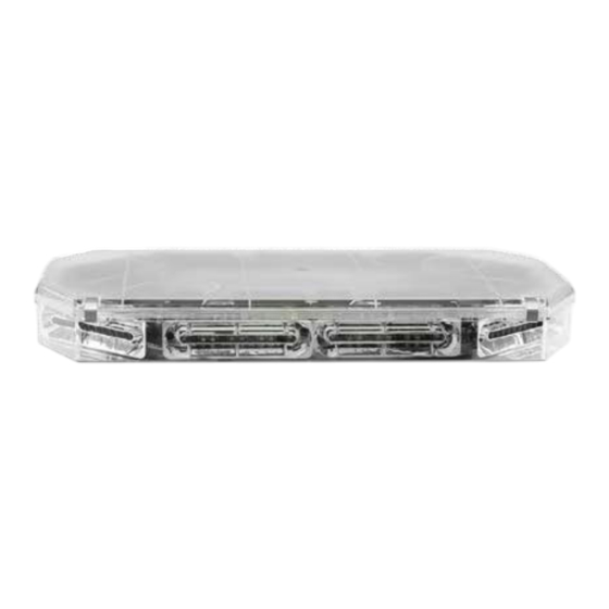
ECCO 27 Series Lightbars are versatile and powerful warning devices suitable for a range of vehicle types and duties. There are numerous
options and lengths available and the lightbars can either be mounted permanently to the vehicle or mounted using an optional roof
mounting kit. The 27 Series is suitable for many vehicle applications and features reflective LED modules, a durable aluminum chassis
and polycarbonate lenses. Available in seven standard configurations, the 27 Series can be configured with either centrally controlled or
independent flashing warning modules, offering a choice of either 3, 8, 12 or 22 LEDs per module, including dual color options. Stop-Tail-
Indicator, worklamp/takedown and alley light modules are also available as well as an integrated Safety Director to control the rear warning
modules independently.
Unpacking and Pre-Installation:
Carefully remove the lightbar and place it on a flat surface. Examine the unit for transit damage and locate all parts. If damage is found or
parts are missing, contact the transit company or ECCO. Do not use damaged or broken parts.
Ensure the lightbar voltage is compatible with the planned installation.
IMPORTANT!
Read all instructions before installing and using. Installer: This manual must be
delivered to the end user. This manual assumes installation by a suitably qualified Automotive Technician.
Installation and Operation Instructions
27 Series IF and CC Lightbars
Page 1 of 18
Advertisement
Table of Contents

Related Manuals for Ecco 27 Series


Summary of Contents for Ecco 27 Series
- Page 1 27 Series IF and CC Lightbars ECCO 27 Series Lightbars are versatile and powerful warning devices suitable for a range of vehicle types and duties. There are numerous options and lengths available and the lightbars can either be mounted permanently to the vehicle or mounted using an optional roof mounting kit.
-
Page 2: Specifications
WARNING! Failure to install or use this product according to manufacturer’s recommendations may result in property damage, serious bodily/personal injury, and/or death to you and those you are seeking to protect! Do not install and/or operate this safety product unless you have read and understand the safety information contained in this manual. - Page 3 Permanent Mounting with Adjustable Mounting Feet 1. Loosen the 5/16” nuts to allow the mounting feet to slide along the base. Place the lightbar over the center of the vehicle and slide the mounting feet into position near the curved edges of the roof when possible. 2.
- Page 4 Permanent Mounting without Adjustable Mounting Feet 1. Insert the four 5/16”-18 carriage bolts in the channels on the under side of the light bar. 2. Place the lightbar over the center of the vehicle and slide the mounting hardware into position near the curved edge when possible as shown in FIGURE 4.
- Page 5 Pylon/Headache Rack Mounting 1. Insert the four (4) 5/16”-18 carriage bolts in the channels on the under side of the light bar and loosely attach the mounting brackets. 2. Place the lightbar on the vehicle and slide the mounting brackets into position. 3.
-
Page 6: Wiring Instructions
Strap Kit Mounting Important! Mounting brackets are specific to the vehicle model. Please make sure the brackets are suitable for the vehicle before installation. 1. Loosen the 5/16” nuts to allow the mounting feet to slide along the base of the lightbar. Loosely attach the mounting strap to each foot using the supplied pan head phillips screws and lock washers. - Page 7 IF Series Wiring An IF series lightbar has a dedicated ground wire and one or more +power wires routed to the modules. The black ground wire should be connected directly to the battery. The amp ratings for each module type are detailed in the specifications section of this installation guide. Before attempting to connect the lightbar wiring harness, refer to the configuration specific wiring key included with the lightbar for the func- tions of each wire.
- Page 8 Dimming Operation 27 Series LED modules may be equipped with a low power “Dimming” mode. When DIM is engaged the LED’s will operate in a reduced power mode which reduces the light output. Use caution when using the DIM setting to ensure that motorists can clearly see the emergency vehicle.
- Page 9 Emergency Mode Flash Pattern Selection There are seven customizable emergency flash pattern modes available based on the wire combinations shown in TABLE 3. When using individual switches, make sure to configure all possible switch combinations. The default setting is unsynchronized which allows each light head module group to be configured separately and the lightbar to flash in an unsynchronized pattern.
- Page 10 Factory Default setting has been restored. For instructions related to the California Title 13 steady burning red warning lamp requirement during level mode operation, please contact ECCO directly. Emergency Mode Flash Pattern Selection – Synchronized The seven customizable emergency flash pattern modes in Table 3 each have the option to be synchronized.
- Page 11 Light Head Group Flash Sequence - Synchronized Order Sequence Left/Right Even/Odd TABLE 8 After the module groups have a sequence selected, a flash pattern rate can be chosen. The default rates are as follows in TABLE 9. Level Mode Default Patterns by Group - Synchronized Light Head Group Flash Rate Front...
- Page 12 Arrowstik Flash Pattern Selection The CC Series Lightbar is designed to offer user selectable traffic directing and traffic warning flash patterns. Each of the ArrowStik® func- tions (LEFT, CENTER-OUT, RIGHT and FLASH) can be programmed individually for unique patterns and flash rates. This allows the greatest flexibility when controlling the various Lightbar configurations available.
- Page 13 Emergency Mode Flash Pattern Selection There are seven customizable emergency flash pattern modes available based on the wire combinations shown in TABLE 15. When using individual switches, make sure to configure all possible switch combinations. Level Mode Combinations Flash Pattern Modes Function Wire Color(s) Default Flash Pattern Pattern...
- Page 14 Variable Rate Picket Fence Single - Front In-Out Quad - Front Cycle - Front Simultaneous Quad - Front TABLE 16 For instructions related to the California Title 13 steady burning red warning lamp requirement during level mode operation, please contact ECCO directly. Page 14 of 18...
- Page 15 Options and Maintenance: Lens Cleaning Occasional cleaning of the lenses will ensure optimum light output. Take care when cleaning lenses - although tough, polycarbonate scratches easily. Clean the lens and base with soap and water or a lens polish using a soft cloth. Do not use solvents as they may damage the polycarbonate.
-
Page 16: Replacement Parts/Accessories
A212708RMK Ford Truck 1/2T 2015-2016 A212709RMK 10 & 14 Series Ford Truck 1/2T 2010-2014 A212710RMK Standard feet, for use with 21 & 27 Series lightbars A2127FT Magnet Mount Kit 22” EZ2122MG Accessories Controller: integrated Safety Director, for use with centrally controlled modules... -
Page 17: Troubleshooting
Troubleshooting: All lightbars are thoroughly tested prior to shipment. However, should you encounter a problem during installation or during the life of the product, follow the guide below for troubleshooting and repair information. If the problem cannot be rectified using the solutions given below, additional information may be obtained from the manufacturer –...
Need help?
Do you have a question about the 27 Series and is the answer not in the manual?
Questions and answers