Table of Contents
Advertisement
Quick Links
www.ti.com
EVM User's Guide: MSPM0C1104 LP-MSPM0C1104
LP-MSPM0C1104 Evaluation Module
Description
The MSPM0C1104 LaunchPad
is an easy-to-use evaluation module for the
MSPM0C1104 microcontroller (MCU). The kit
contains everything needed to start developing
on the MSPM0C110x microcontroller platform,
including onboard debug probe for programming and
debugging. The board also features an onboard
button and LED for quick integration of a simple user
interface.
The MSPM0C1104 is an Arm
-M0+ CPU with frequency up to 24 MHz. The
device features 16KB of embedded flash memory
combined with 1KB of on-chip RAM. This devices
includes an integrated 12-bit 866Ksps SAR ADC
with 10 external channels. Rapid prototyping is
simplified by the 20-pin BoosterPack
headers, which support a wide range of available
BoosterPack plug-in modules. Users can quickly add
features like wireless connectivity, graphical displays,
environmental sensing, and much more. Design a
BoosterPack plug-in module or choose among many
available from TI and third-party developers.
Get Started
1. Order
LP-MSPM0C1104
2. Navigate to
dev.ti.com
examples.
SLAU908 – OCTOBER 2023
Submit Document Feedback
™
Development Kit
®
Cortex
®
32-bit
™
plug-in module
from ti.com.
to browse for code
Copyright © 2023 Texas Instruments Incorporated
3. Plug LP-MSPMC1104 into a PC with the provided
USB cable.
4. Download code directly from the browser to the
MSPM0C1104 with CCS Cloud.
5. Download CCS Theia for a desktop integrated
development environment.
Features
•
Onboard XDS110 debug probe
•
Backchannel UART through USB to PC
•
USB powered
•
20-pin BoosterPack headers
•
RC filter for ADC input or PWM DAC output
•
One user button
•
One red LED
Applications
•
Battery charging and management
•
Power supplies and power delivery
•
Personal electronics
•
Building security and fire safety
•
Connected peripherals and printers
•
Grid infrastructure
•
Smart metering
•
Communication modules
•
Medical and healthcare
•
Lighting
LP-MSPM0C1104 Evaluation Module
Description
1
Advertisement
Table of Contents

Related Manuals for Texas Instruments LP-MSPM0C1104


Summary of Contents for Texas Instruments LP-MSPM0C1104
- Page 1 Description EVM User's Guide: MSPM0C1104 LP-MSPM0C1104 LP-MSPM0C1104 Evaluation Module 3. Plug LP-MSPMC1104 into a PC with the provided Description USB cable. ™ The MSPM0C1104 LaunchPad Development Kit 4. Download code directly from the browser to the is an easy-to-use evaluation module for the MSPM0C1104 with CCS Cloud.
-
Page 2: Kit Contents
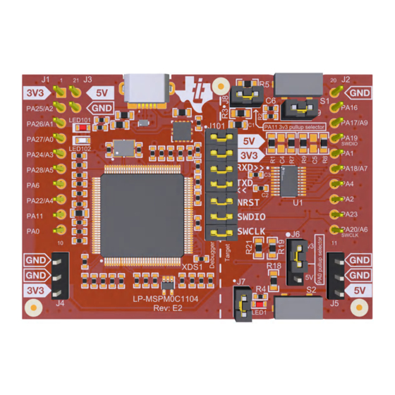
GUI. See the out-of-box description below. Once the code has been flashed onto LP-MSPM0C1104, the device can be powered from a power supply other than the built in USB power supply. This allows the user to forgo the PC connection. Power can be applied directly to either the 3.3V or 5 V rails. - Page 3 Figure 2-1. Diagram of LP-MSPM0C1104 Jumpers and Connectors LP-MSPM0C1104 has many hardware features, which allow the user full access to the MSPM0C1104 pins while still providing onboard connectivity for easy use. Shunt connections provide a way for the user to easily change the LaunchPad configuration.
-
Page 4: Power Requirements
2.2 Power Requirements Simple nature of LP-MSPM0C1104 only requires 5 V USB power to operate. The onboard LDO generates a 3.3V supply up to 500 mA. The LaunchPad can also be power directly from the BoosterPack or power headers using a bench supply or battery. - Page 5 PC application configuring the baud rate to be the same as what is configured on the UART0 is important. SLAU908 – OCTOBER 2023 LP-MSPM0C1104 Evaluation Module Submit Document Feedback Copyright © 2023 Texas Instruments Incorporated...
- Page 6 BoosterPack plug-in module with the LaunchPad development kit to verify compatibility. Conflicts can be resolved by changing the MSPM0C1104 device pin function configuration in software. LP-MSPM0C1104 Evaluation Module SLAU908 – OCTOBER 2023 Submit Document Feedback Copyright © 2023 Texas Instruments Incorporated...
- Page 7 Get started right away with the out-of-box example on LP-MSPM0C1104. Simply navigate to the Out-of-box GUI and plug in LP-MSPM0C1104 to a PC, Mac, or Linux workstation. This GUI provides control of the built in LED and a dashboard of the current state of LP-MSPM0C1104. Find instructions to start prototyping below.
- Page 8 PA20/A6/SWCLK PA26/A0_1 /TIMG8_C0/UART0_RX/SPI0_POCI/BEEP/TIMG0_C0/TIMA_FAL0 PA22_A4 PA27_UART_TX_A0 PA22/A4 PA27/A0_0/TIMG8_C1/SPI0_CS3/TIMA0_C0N/UART0_TX/SPI0_POCI/TIMA_FAL2 PA23 RESET Button PA23/VREF+ PA24_A3 PA24/A3 PA25_A2 PA25/A2 PA26_UART_RX_A1 PA26/A1 PA27_UART_TX_A0 PA27/A0 MSPM0C1104SRUK 0.01uF MSPM0L1306SDGS20 Figure 4-1. LP-MSPM0C1104 Evaluation Module SLAU908 – OCTOBER 2023 Submit Document Feedback Copyright © 2023 Texas Instruments Incorporated...
- Page 9 XDS_ID XDS_USB_D_N 1.00M 3300pF ITMS XDS_VCC XDS_VBUS TPD4E004DRYR ITCK LDO 3v3 (for XDS) ITDO XDS_VCC ITDI 2.2uF IRSTN TP10 XDS_VCC TPS73533DRBT Figure 4-3. Schematic SLAU908 – OCTOBER 2023 LP-MSPM0C1104 Evaluation Module Submit Document Feedback Copyright © 2023 Texas Instruments Incorporated...
- Page 10 Assembly Note These assemblies must be clean and free from flux and all contaminants. Use of no clean flux is not acceptable. Figure 4-4. LP-MSPM0C1104 Evaluation Module SLAU908 – OCTOBER 2023 Submit Document Feedback Copyright © 2023 Texas Instruments Incorporated...
-
Page 11: Pcb Layouts
Hardware Design Files 4.2 PCB Layouts Figure 4-5. Layer 1: Top, Signal and Power Figure 4-6. Layer 2: Ground SLAU908 – OCTOBER 2023 LP-MSPM0C1104 Evaluation Module Submit Document Feedback Copyright © 2023 Texas Instruments Incorporated... - Page 12 Hardware Design Files www.ti.com Figure 4-7. Layer 3: Ground Figure 4-8. Layer 4: Bottom, Signal LP-MSPM0C1104 Evaluation Module SLAU908 – OCTOBER 2023 Submit Document Feedback Copyright © 2023 Texas Instruments Incorporated...
-
Page 13: Bill Of Materials (Bom)
100mil, Tin Solutions J7, J8, J9 Header, 100mil, 2x1, Tin, TH Header 2x1 90120-0122 Molex J101 Header, 100mil, 7x2, Gold, TH 7x2 Header TSW-107-07-G-D Samtec SLAU908 – OCTOBER 2023 LP-MSPM0C1104 Evaluation Module Submit Document Feedback Copyright © 2023 Texas Instruments Incorporated... - Page 14 11-12 Black J101: Shunt, 100mil, Gold plated, SH-J7 Shunt SNT-100-BK-G Samtec 12-13 Black Shunt, 100mil, Gold plated, SH-J8 J6: 1-2 Shunt SNT-100-BK-G Samtec Black LP-MSPM0C1104 Evaluation Module SLAU908 – OCTOBER 2023 Submit Document Feedback Copyright © 2023 Texas Instruments Incorporated...
-
Page 15: Additional Information
Apple Inc. ® Linux is a registered trademark of Linus Torvalds. All trademarks are the property of their respective owners. SLAU908 – OCTOBER 2023 LP-MSPM0C1104 Evaluation Module Submit Document Feedback Copyright © 2023 Texas Instruments Incorporated... - Page 16 STANDARD TERMS FOR EVALUATION MODULES Delivery: TI delivers TI evaluation boards, kits, or modules, including any accompanying demonstration software, components, and/or documentation which may be provided together or separately (collectively, an “EVM” or “EVMs”) to the User (“User”) in accordance with the terms set forth herein.
- Page 17 www.ti.com Regulatory Notices: 3.1 United States 3.1.1 Notice applicable to EVMs not FCC-Approved: FCC NOTICE: This kit is designed to allow product developers to evaluate electronic components, circuitry, or software associated with the kit to determine whether to incorporate such items in a finished product and software developers to write software applications for use with the end product.
- Page 18 www.ti.com Concernant les EVMs avec antennes détachables Conformément à la réglementation d'Industrie Canada, le présent émetteur radio peut fonctionner avec une antenne d'un type et d'un gain maximal (ou inférieur) approuvé pour l'émetteur par Industrie Canada. Dans le but de réduire les risques de brouillage radioélectrique à...
- Page 19 www.ti.com EVM Use Restrictions and Warnings: 4.1 EVMS ARE NOT FOR USE IN FUNCTIONAL SAFETY AND/OR SAFETY CRITICAL EVALUATIONS, INCLUDING BUT NOT LIMITED TO EVALUATIONS OF LIFE SUPPORT APPLICATIONS. 4.2 User must read and apply the user guide and other available documentation provided by TI regarding the EVM prior to handling or using the EVM, including without limitation any warning or restriction notices.
- Page 20 Notwithstanding the foregoing, any judgment may be enforced in any United States or foreign court, and TI may seek injunctive relief in any United States or foreign court. Mailing Address: Texas Instruments, Post Office Box 655303, Dallas, Texas 75265 Copyright © 2023, Texas Instruments Incorporated...
-
Page 21: Important Notice
TI products. TI’s provision of these resources does not expand or otherwise alter TI’s applicable warranties or warranty disclaimers for TI products. TI objects to and rejects any additional or different terms you may have proposed. IMPORTANT NOTICE Mailing Address: Texas Instruments, Post Office Box 655303, Dallas, Texas 75265 Copyright © 2023, Texas Instruments Incorporated...
Need help?
Do you have a question about the LP-MSPM0C1104 and is the answer not in the manual?
Questions and answers