Table of Contents
Advertisement
Quick Links
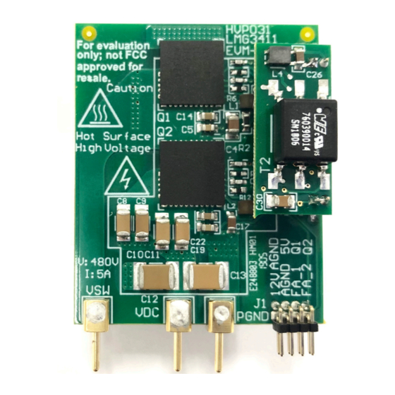
The LMG3410EVM-031 features two LMG3410R150 600V GaN power transistors with integrated drivers
that are configured in a half bridge with all the required bias circuit and logic/power level shifting. Essential
power stage and gate driving high frequency current loops are fully enclosed on the board to minimize
parasitic inductances, reducing voltage overshoots and improving performance. The LMG3410EVM-031 is
configured to have a socket style external connection for easy interface with external power stages to run
the LMG3410R150 in various applications.
1
....................................................................................................................
2
.....................................................................................................................
3
...................................................................................................................
4
5
6
7
EVM Assembly Drawing and PCB Layout
8
Bill of Materials
1
Simplified LMG3410EVM-031 Schematic
2
Top Side View of LMG3410EVM-031
3
Back Side View of LMG3410EVM-031
4
Top Side View of LMG3410EVM-031 in Isolated Power Supply Configuration
5
Back Side View of LMG3410EVM-031 in Isolated Power Supply Configuration
6
LMG3410EVM-031 Schematic
7
Recommended Footprint for LMG3410EVM-031
8
LMG34XX-BB-EVM Schematic
9
LMG3410EVM-031 Connected with LMG34XX-BB-EVM
10
Recommended Connection Points
11
12
13
14
15
16
17
18
19
20
21
22
SNOU168 - June 2019
Submit Documentation Feedback
LMG3410R150-031 EVM User Guide
.............................................................................................................
.....................................................................................................
..............................................................................
.............................................................................................................
................................................................................
.....................................................................................
...................................................................................
.............................................................................................
..........................................................................................
.......................................................................................
..............................................................................
..............................................................................
Copyright © 2019, Texas Instruments Incorporated
Contents
List of Figures
......................................................................
............................................................
..................................................................
...................................................
...................................................................
......................................................................
..................................................................
......................................................................
..................................................................
LMG3410R150-031 EVM User Guide
User's Guide
SNOU168 - June 2019
..................
.....................................
....................................
.....................................
.......................
.......................
3
5
9
12
15
16
18
21
5
6
6
7
7
9
10
11
12
13
16
16
16
16
16
16
18
18
19
19
20
20
1
Advertisement
Table of Contents

Related Manuals for Texas Instruments LMG3410R150-031 EVM


Summary of Contents for Texas Instruments LMG3410R150-031 EVM
-
Page 1: Table Of Contents
LMG3410EVM-031 Inner Copper Layer 2 ..............LMG3410EVM-031 Bottom Layer and Components ..............LMG34XX-BB-EVM Top Layer and Components ..............LMG34XX-BB-EVM Bottom Layer and Components SNOU168 – June 2019 LMG3410R150-031 EVM User Guide Submit Documentation Feedback Copyright © 2019, Texas Instruments Incorporated... - Page 2 List of Terminals ..................LMG3410EVM-031 List of Materials ..................LMG34XX-BB-EVM List of Materials Trademarks All trademarks are the property of their respective owners. LMG3410R150-031 EVM User Guide SNOU168 – June 2019 Submit Documentation Feedback Copyright © 2019, Texas Instruments Incorporated...
-
Page 3: Lmg3410Evm-031 User's Guide General Ti High Voltage Evaluation User Safety Guidelines
Any other use and/or application are strictly prohibited by Texas Instruments. If you are not suitably qualified, you must immediately stop from further use of the HV EVM. - Page 4 Board must be handled with care by a professional. For safety, use of isolated test equipment with overvoltage and overcurrent protection is highly recommended. LMG3410R150-031 EVM User Guide SNOU168 – June 2019 Submit Documentation Feedback Copyright © 2019, Texas Instruments Incorporated...
-
Page 5: Description
Input DC voltage of the half bridge PGND Power ground of the half bridge. Connected to AGND. LMG3410 FA_1 FAULT LMG3410 FA_2 FAULT PGND Figure 1. Simplified LMG3410EVM-031 Schematic SNOU168 – June 2019 LMG3410R150-031 EVM User Guide Submit Documentation Feedback Copyright © 2019, Texas Instruments Incorporated... - Page 6 The two copper pads have high voltage potential difference between them so an electrically isolative thermal interface material (TIM) is required. Please refer to Section 8 for the recommended TIM and mechanical fixture. LMG3410R150-031 EVM User Guide SNOU168 – June 2019 Submit Documentation Feedback Copyright © 2019, Texas Instruments Incorporated...
- Page 7 Figure 4. Top Side View of LMG3410EVM-031 in Isolated Power Supply Configuration Figure 5. Back Side View of LMG3410EVM-031 in Isolated Power Supply Configuration SNOU168 – June 2019 LMG3410R150-031 EVM User Guide Submit Documentation Feedback Copyright © 2019, Texas Instruments Incorporated...
- Page 8 PWM disable in the event of a fault from the LMG3410EVM-031 • Maximum recommended operating voltage of 480V and absolute maximum voltage of 600V • Maximum recommended operating inductor current of 5A LMG3410R150-031 EVM User Guide SNOU168 – June 2019 Submit Documentation Feedback Copyright © 2019, Texas Instruments Incorporated...
-
Page 9: Schematic
4.7uF IN Pin on daughter board 0.1uF 4.7uF OUT Pin on daughter board 4.7uF -ISO_RET_H_AO AGND_AI SN6505 DIODE_SCHOTTKY ISO_RET_H_B Figure 6. LMG3410EVM-031 Schematic SNOU168 – June 2019 LMG3410R150-031 EVM User Guide Submit Documentation Feedback Copyright © 2019, Texas Instruments Incorporated... - Page 10 Schematic www.ti.com Figure 7. Recommended Footprint for LMG3410EVM-031 LMG3410R150-031 EVM User Guide SNOU168 – June 2019 Submit Documentation Feedback Copyright © 2019, Texas Instruments Incorporated...
- Page 11 1µF 10µF 47µH 282834-2 AGND1 AGND PGND PGND Green PGND2 AGND ACMGND AGND2 Copyright © 2016, Texas Instruments Incorporated Figure 8. LMG34XX-BB-EVM Schematic SNOU168 – June 2019 LMG3410R150-031 EVM User Guide Submit Documentation Feedback Copyright © 2019, Texas Instruments Incorporated...
-
Page 12: Test Setup
Fan: 200 LFM minimum airflow is recommended. Recommended Test Setup The LMG3410EVM-031 connects to the LMG34XX-BB-EVM as Figure 9 shows. Figure 9. LMG3410EVM-031 Connected with LMG34XX-BB-EVM LMG3410R150-031 EVM User Guide SNOU168 – June 2019 Submit Documentation Feedback Copyright © 2019, Texas Instruments Incorporated... - Page 13 To minimize the risk of the electrical shock and burn hazard, precautions must be taken when handling the board due to the high voltages and elevated temperatures on the EVM. SNOU168 – June 2019 LMG3410R150-031 EVM User Guide Submit Documentation Feedback Copyright © 2019, Texas Instruments Incorporated...
-
Page 14: Test Point Functional Description
Single 0 V to 5 V PWM input for gate LOGIC Header to connect PWM, FAULT logic HB Card PIN Connector to interface LMG3410EVM-031 board LMG3410R150-031 EVM User Guide SNOU168 – June 2019 Submit Documentation Feedback Copyright © 2019, Texas Instruments Incorporated... -
Page 15: Test Procedure
Fault protection on the LMG34XX-BB-EVM is not latching, so if a fault clears and the LMG34XX-BB- EVM is still operational PWM will resume. SNOU168 – June 2019 LMG3410R150-031 EVM User Guide Submit Documentation Feedback Copyright © 2019, Texas Instruments Incorporated... -
Page 16: Typical Characteristics
Voltage Switch Node Figure 14. Switching Waveforms with 400V Input, 100kHz, 30% Duty Cycle, 4A Output Figure 13. Recommended Configuration for Heatsink and LMG3410R150-031 EVM User Guide SNOU168 – June 2019 Submit Documentation Feedback Copyright © 2019, Texas Instruments Incorporated... -
Page 17: Low To High Transition Waveform With 400V Input, 100Khz, 30% Duty Cycle, 4A Output
Figure 15. Low to High Transition Waveform with 400V Input, 100kHz, 30% Duty Cycle, 4A Output Input, 100kHz, 30% Duty Cycle, 4A Output SNOU168 – June 2019 LMG3410R150-031 EVM User Guide Submit Documentation Feedback Copyright © 2019, Texas Instruments Incorporated... -
Page 18: Lmg3410Evm-031 Top Layer And Components
EVM Assembly Drawing and PCB Layout www.ti.com EVM Assembly Drawing and PCB Layout Figure 17. LMG3410EVM-031 Top Layer and Components Figure 18. LMG3410EVM-031 Inner Copper Layer 1 LMG3410R150-031 EVM User Guide SNOU168 – June 2019 Submit Documentation Feedback Copyright © 2019, Texas Instruments Incorporated... -
Page 19: Lmg3410Evm-031 Inner Copper Layer 2
EVM Assembly Drawing and PCB Layout www.ti.com Figure 19. LMG3410EVM-031 Inner Copper Layer 2 Figure 20. LMG3410EVM-031 Bottom Layer and Components SNOU168 – June 2019 LMG3410R150-031 EVM User Guide Submit Documentation Feedback Copyright © 2019, Texas Instruments Incorporated... -
Page 20: Lmg34Xx-Bb-Evm Top Layer And Components
EVM Assembly Drawing and PCB Layout www.ti.com Figure 21. LMG34XX-BB-EVM Top Layer and Components Figure 22. LMG34XX-BB-EVM Bottom Layer and Components LMG3410R150-031 EVM User Guide SNOU168 – June 2019 Submit Documentation Feedback Copyright © 2019, Texas Instruments Incorporated... -
Page 21: Lmg3410Evm-031 List Of Materials
Fiducial mark. There is nothing to buy or mount. FID4, FID5, FID6 J4, J5 Receptacle, 1.27mm, 2x1, Gold with Tin tail, SMT M50-3140245 Harwin SNOU168 – June 2019 LMG3410R150-031 EVM User Guide Submit Documentation Feedback Copyright © 2019, Texas Instruments Incorporated... -
Page 22: Lmg34Xx-Bb-Evm List Of Materials
Dual Schmitt-Trigger Inverter, DCK0006A SN74LVC2G14DCKR Texas Instruments Dual 2-input Positive-and Gate, DCT0008A SN74LVC2G08IDCTRQ1 Texas Instruments 1A Low Dropout Regulator, 4-pin SOT-223, LM2940IMP-5.0/NOPB Texas Instruments Pb-Free LMG3410R150-031 EVM User Guide SNOU168 – June 2019 Submit Documentation Feedback Copyright © 2019, Texas Instruments Incorporated... - Page 23 STANDARD TERMS FOR EVALUATION MODULES Delivery: TI delivers TI evaluation boards, kits, or modules, including any accompanying demonstration software, components, and/or documentation which may be provided together or separately (collectively, an “EVM” or “EVMs”) to the User (“User”) in accordance with the terms set forth herein.
- Page 24 www.ti.com Regulatory Notices: 3.1 United States 3.1.1 Notice applicable to EVMs not FCC-Approved: FCC NOTICE: This kit is designed to allow product developers to evaluate electronic components, circuitry, or software associated with the kit to determine whether to incorporate such items in a finished product and software developers to write software applications for use with the end product.
- Page 25 www.ti.com Concernant les EVMs avec antennes détachables Conformément à la réglementation d'Industrie Canada, le présent émetteur radio peut fonctionner avec une antenne d'un type et d'un gain maximal (ou inférieur) approuvé pour l'émetteur par Industrie Canada. Dans le but de réduire les risques de brouillage radioélectrique à...
- Page 26 www.ti.com EVM Use Restrictions and Warnings: 4.1 EVMS ARE NOT FOR USE IN FUNCTIONAL SAFETY AND/OR SAFETY CRITICAL EVALUATIONS, INCLUDING BUT NOT LIMITED TO EVALUATIONS OF LIFE SUPPORT APPLICATIONS. 4.2 User must read and apply the user guide and other available documentation provided by TI regarding the EVM prior to handling or using the EVM, including without limitation any warning or restriction notices.
- Page 27 Notwithstanding the foregoing, any judgment may be enforced in any United States or foreign court, and TI may seek injunctive relief in any United States or foreign court. Mailing Address: Texas Instruments, Post Office Box 655303, Dallas, Texas 75265 Copyright © 2019, Texas Instruments Incorporated...
- Page 28 TI products. TI’s provision of these resources does not expand or otherwise alter TI’s applicable warranties or warranty disclaimers for TI products. Mailing Address: Texas Instruments, Post Office Box 655303, Dallas, Texas 75265 Copyright © 2019, Texas Instruments Incorporated...
Need help?
Do you have a question about the LMG3410R150-031 EVM and is the answer not in the manual?
Questions and answers