Table of Contents
Advertisement
Quick Links
www.ti.com
User's Guide
LM5123EVM-BST Evaluation Module
The LM5123EVM-BST evaluation module showcases the features and performance of the LM5123-Q1 wide
input voltage synchronous boost controller. The standard configuration is designed to provide a regulated output
of 24-V at 200-W, from an input voltage of 8-V to 18-V and switching at 440 kHz. The output voltage can be
dynamically up to 33-V using the TRK pin of the LM5123-Q1.
This EVM is designed for ease of configuration, enabling an user to evaluate many different applications on
the same module. Functionality includes: low I
when V
is greater than V
IN
frequency dithering, programmable undervoltage lock out (UVLO), and overvoltage protection.
1
Introduction.............................................................................................................................................................................3
1.1
Applications........................................................................................................................................................................3
1.2 Features.............................................................................................................................................................................
2 EVM Setup...............................................................................................................................................................................
Characteristics...........................................................................................................................................................5
2.2 EVM Connectors and Test Points......................................................................................................................................
2.3 EVM Configurations...........................................................................................................................................................
Procedures....................................................................................................................................................8
3.1 Equipment..........................................................................................................................................................................
Results.............................................................................................................................................................................9
...........................................................................................................................................................................9
4.2 Load Regulation ..............................................................................................................................................................
4.3 Thermal Performance......................................................................................................................................................
Waveforms..........................................................................................................................................................11
4.5 Steady State Operation....................................................................................................................................................
4.6 Load Transient Response................................................................................................................................................
Tracking...................................................................................................................................................13
Layers............................................................................................................................................................................14
6
Schematic..............................................................................................................................................................................16
7 Bill of Materials.....................................................................................................................................................................
8 Revision History...................................................................................................................................................................
Figure 1-1. Typical Application Circuit.........................................................................................................................................
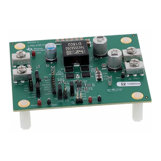
Figure 2-1. EVM Photo................................................................................................................................................................
Figure 2-2. Fixed Output Voltage Configuration..........................................................................................................................
Figure 2-3. Variable Output Voltage Configuration .....................................................................................................................
Setup.........................................................................................................................................................8
OUT
OUT
Regulation..............................................................................................................................................10
OUT
= 14-V, V
OUT
OUT
SNVU737A - DECEMBER 2020 - REVISED DECEMBER 2021
Submit Document Feedback
operation, internal feedback resistors, bypass mode operation
Q
, dynamic output voltage tracking, power good (PGOOD) indicator, programmable
OUT
Table of Contents
List of Figures
= 24-V.............................................................................................................................................
= 24-V Light
Load............................................................................................................................9
= 8-V, V
= 24-V P
IN
OUT
= 24-V, P
= 200-W....................................................................................................................
OUT
= 200-W..................................................................................................................
= 24-V, P
= 200-W..................................................................................................................
OUT
= 200-W..................................................................................................................
= 24-V, P
= 200-W....................................................................................................................
OUT
= 200-W................................................................................................................
Copyright © 2021 Texas Instruments Incorporated
ABSTRACT
= 200-W, No Forced Airflow.................................................
OUT
Table of Contents
LM5123EVM-BST Evaluation Module
3
4
5
7
8
10
10
11
12
17
21
3
4
7
7
9
10
11
11
11
11
11
11
1
Advertisement
Table of Contents

Related Manuals for Texas Instruments LM5123EVM-BST


Summary of Contents for Texas Instruments LM5123EVM-BST
-
Page 1: Table Of Contents
LM5123EVM-BST Evaluation Module ABSTRACT The LM5123EVM-BST evaluation module showcases the features and performance of the LM5123-Q1 wide input voltage synchronous boost controller. The standard configuration is designed to provide a regulated output of 24-V at 200-W, from an input voltage of 8-V to 18-V and switching at 440 kHz. The output voltage can be dynamically up to 33-V using the TRK pin of the LM5123-Q1. - Page 2 Table 2-3. Programmable Jumper Connections.......................... Table 2-4. Probe Points................................Table 7-1. Bill of Materials................................17 Trademarks All trademarks are the property of their respective owners. LM5123EVM-BST Evaluation Module SNVU737A – DECEMBER 2020 – REVISED DECEMBER 2021 Submit Document Feedback Copyright © 2021 Texas Instruments Incorporated...
-
Page 3: Introduction
Introduction 1 Introduction The LM5123EVM-BST evaluation module is designed to evaluate the operation and performance of the LM5123-Q1 low-I synchronous boost controller. The EVM operates over an input voltage range of 8-V to 18-V and can handle input transients up to 42-V. The EVM provides a 24-V output with a maximum power rating of 200-W. -
Page 4: Evm Setup
Prolonged operation with low input at full power will cause heating of Q3 and Q2. Board surface is hot. Do not touch! Contact may cause burns. LM5123EVM-BST Evaluation Module SNVU737A – DECEMBER 2020 – REVISED DECEMBER 2021 Submit Document Feedback Copyright © 2021 Texas Instruments Incorporated... -
Page 5: Evm Characteristics
1 and pin 2 Open Dithering is enabled. To synchronize to an external clock C33 should be removed. SNVU737A – DECEMBER 2020 – REVISED DECEMBER 2021 LM5123EVM-BST Evaluation Module Submit Document Feedback Copyright © 2021 Texas Instruments Incorporated... -
Page 6: Table 2-4. Probe Points
Power ground connection PGND Power ground connection Probe point for many of the LM5123 control signals BIAS PGOOD UVLO COMP AGND LM5123EVM-BST Evaluation Module SNVU737A – DECEMBER 2020 – REVISED DECEMBER 2021 Submit Document Feedback Copyright © 2021 Texas Instruments Incorporated... -
Page 7: Evm Configurations
2.3.1 Output Voltage Tracking Section 2.3.1describes how to setup the evaluation module for dynamic output voltage tracking. The LM5123EVM-BST is typically configured to have fixed output voltage of 24 V. Figure 2-2 shows the resistor divider connection from the REF pin to the TRK pin that sets the output voltage to 24 V. R... -
Page 8: Test Setup And Procedures
Electronic Load IOUT VOUT Figure 3-1. EVM Test Setup 3.1 Equipment The following test equipment is needed to test the LM5123EVM-BST as shown in Figure 3-1. • Power supply: The input voltage source (V ) should be a variable supply. The power supply should source 7-V to 36-V and be able to supply more than 30-A of current. -
Page 9: Test Results
Skip switching mode and FPWM switching mode at light loading conditions. SKIP MODE FPWM MODE 0.001 0.021 0.041 0.061 0.081 Figure 4-2. Efficiency: V = 24-V Light Load SNVU737A – DECEMBER 2020 – REVISED DECEMBER 2021 LM5123EVM-BST Evaluation Module Submit Document Feedback Copyright © 2021 Texas Instruments Incorporated... -
Page 10: Load Regulation
Figure 4-3. 24-V Load Regulation 4.3 Thermal Performance Figure 4-4. Thermal Performance: V = 8-V, V = 24-V P = 200-W, No Forced Airflow LM5123EVM-BST Evaluation Module SNVU737A – DECEMBER 2020 – REVISED DECEMBER 2021 Submit Document Feedback Copyright © 2021 Texas Instruments Incorporated... -
Page 11: Start-Up Waveforms
= 24-V, P = 200-W 4.5 Steady State Operation Full load operation Figure 4-9 through Figure 4-12 show the steady state waveforms of the LM5123EVM-BST. Figure 4-9. V = 8-V, V = 24-V, P = 200-W Figure 4-10. V = 10-V, V... -
Page 12: Load Transient Response
Figure 4-15. V = 14-V, I = 4-A to 8-A Figure 4-16. V = 18-V, I = 4-A to 8-A LM5123EVM-BST Evaluation Module SNVU737A – DECEMBER 2020 – REVISED DECEMBER 2021 Submit Document Feedback Copyright © 2021 Texas Instruments Incorporated... -
Page 13: Output Voltage Tracking
Figure 4-18. Sine Voltage Tracking, V = 14-V, P = 200-W, V 14-V to 33-V = 200-W, V 14-V to 33-V SNVU737A – DECEMBER 2020 – REVISED DECEMBER 2021 LM5123EVM-BST Evaluation Module Submit Document Feedback Copyright © 2021 Texas Instruments Incorporated... -
Page 14: Pcb Layers
Figure 5-1. Layout: Top Silk Screen Figure 5-2. Layout: Top Layer Figure 5-4. Layout: Signal Layer 2 Figure 5-3. Layout: Signal Layer 1 LM5123EVM-BST Evaluation Module SNVU737A – DECEMBER 2020 – REVISED DECEMBER 2021 Submit Document Feedback Copyright © 2021 Texas Instruments Incorporated... -
Page 15: Figure 5-5. Layout: Bottom Layer
PCB Layers Figure 5-6. Layout: Bottom Silk Screen Figure 5-5. Layout: Bottom Layer SNVU737A – DECEMBER 2020 – REVISED DECEMBER 2021 LM5123EVM-BST Evaluation Module Submit Document Feedback Copyright © 2021 Texas Instruments Incorporated... -
Page 16: Schematic
Schematic www.ti.com 6 Schematic Figure 6-1 illustrates the EVM schematic. Figure 6-1. Schematic LM5123EVM-BST Evaluation Module SNVU737A – DECEMBER 2020 – REVISED DECEMBER 2021 Submit Document Feedback Copyright © 2021 Texas Instruments Incorporated... -
Page 17: Bill Of Materials
CGA3E3X7R1H224K080AB AEC-Q200 Grade 1, 0603 C41, C42 6800pF CAP, CERM, 6800 pF, 50 V,+/- 5%, C0G/ GRM1885C1H682JA01D MuRata NP0, 0603 SNVU737A – DECEMBER 2020 – REVISED DECEMBER 2021 LM5123EVM-BST Evaluation Module Submit Document Feedback Copyright © 2021 Texas Instruments Incorporated... - Page 18 RES, 86.6 k, 1%, 0.1 W, 0603 RC0603FR-0786K6L Yageo 1.00k RES, 1.00 k, 1%, 0.1 W, AEC-Q200 Grade 0, CRCW06031K00FKEA Vishay-Dale 0603 LM5123EVM-BST Evaluation Module SNVU737A – DECEMBER 2020 – REVISED DECEMBER 2021 Submit Document Feedback Copyright © 2021 Texas Instruments Incorporated...
- Page 19 RES, 2.00, 1%, 0.5 W, AEC-Q200 Grade 0, 1210 ERJ-14BQF2R0U Panasonic 1210 100k RES, 100 k, 1%, 0.1 W, AEC-Q200 Grade 0, CRCW0603100KFKEA Vishay-Dale 0603 SNVU737A – DECEMBER 2020 – REVISED DECEMBER 2021 LM5123EVM-BST Evaluation Module Submit Document Feedback Copyright © 2021 Texas Instruments Incorporated...
- Page 20 RES, 80.6 k, 1%, 0.1 W, AEC-Q200 Grade 0, CRCW060380K6FKEA Vishay-Dale 0603 24.9k RES, 24.9 k, 0.1%, 0.1 W, 0603 RT0603BRD0724K9L Yageo America LM5123EVM-BST Evaluation Module SNVU737A – DECEMBER 2020 – REVISED DECEMBER 2021 Submit Document Feedback Copyright © 2021 Texas Instruments Incorporated...
-
Page 21: Revision History
Changes from Revision * (December 2020) to Revision A (December 2021) Page • Updated text to match the proper rating of the EVM..................• Updated images throughout the user's guide..................... SNVU737A – DECEMBER 2020 – REVISED DECEMBER 2021 LM5123EVM-BST Evaluation Module Submit Document Feedback Copyright © 2021 Texas Instruments Incorporated... - Page 22 STANDARD TERMS FOR EVALUATION MODULES Delivery: TI delivers TI evaluation boards, kits, or modules, including any accompanying demonstration software, components, and/or documentation which may be provided together or separately (collectively, an “EVM” or “EVMs”) to the User (“User”) in accordance with the terms set forth herein.
- Page 23 www.ti.com Regulatory Notices: 3.1 United States 3.1.1 Notice applicable to EVMs not FCC-Approved: FCC NOTICE: This kit is designed to allow product developers to evaluate electronic components, circuitry, or software associated with the kit to determine whether to incorporate such items in a finished product and software developers to write software applications for use with the end product.
- Page 24 www.ti.com Concernant les EVMs avec antennes détachables Conformément à la réglementation d'Industrie Canada, le présent émetteur radio peut fonctionner avec une antenne d'un type et d'un gain maximal (ou inférieur) approuvé pour l'émetteur par Industrie Canada. Dans le but de réduire les risques de brouillage radioélectrique à...
- Page 25 www.ti.com EVM Use Restrictions and Warnings: 4.1 EVMS ARE NOT FOR USE IN FUNCTIONAL SAFETY AND/OR SAFETY CRITICAL EVALUATIONS, INCLUDING BUT NOT LIMITED TO EVALUATIONS OF LIFE SUPPORT APPLICATIONS. 4.2 User must read and apply the user guide and other available documentation provided by TI regarding the EVM prior to handling or using the EVM, including without limitation any warning or restriction notices.
- Page 26 Notwithstanding the foregoing, any judgment may be enforced in any United States or foreign court, and TI may seek injunctive relief in any United States or foreign court. Mailing Address: Texas Instruments, Post Office Box 655303, Dallas, Texas 75265 Copyright © 2019, Texas Instruments Incorporated...
- Page 27 TI products. TI’s provision of these resources does not expand or otherwise alter TI’s applicable warranties or warranty disclaimers for TI products. TI objects to and rejects any additional or different terms you may have proposed. IMPORTANT NOTICE Mailing Address: Texas Instruments, Post Office Box 655303, Dallas, Texas 75265 Copyright © 2021, Texas Instruments Incorporated...
Need help?
Do you have a question about the LM5123EVM-BST and is the answer not in the manual?
Questions and answers