Table of Contents
Advertisement
Quick Links
MASTERFLEX
I/P
MFLX7421-00
®
®
(US & Canada only) Toll Free 1-800-MASTERFLEX • 1-800-637-3739
(Outside US & Canada) 1-847-381-7050
masterflex.tech@avantorsciences.com | www.avantorsciences.com/masterflex
OPERATING MANUAL:
MASTERFLEX
MASTERSENSE™
PROCESS DRIVES
Model Nos.
MFLX77421-00
MFLX77421-02
I/P
®
®
A-1299-5221
Edition 02
Advertisement
Table of Contents

Related Manuals for Masterflex I/P MASTERSENSE MFLX77421-00


Summary of Contents for Masterflex I/P MASTERSENSE MFLX77421-00
- Page 1 OPERATING MANUAL: MASTERFLEX ® ® MASTERSENSE™ PROCESS DRIVES Model Nos. MFLX77421-00 MFLX77421-02 MASTERFLEX MFLX7421-00 ® ® A-1299-5221 Edition 02 (US & Canada only) Toll Free 1-800-MASTERFLEX • 1-800-637-3739 (Outside US & Canada) 1-847-381-7050 masterflex.tech@avantorsciences.com | www.avantorsciences.com/masterflex...
- Page 2 ® symbol in this publication are registered in the US and in other countries. MasterSense™ EtherNet/IP™ is a trademark of ODVA Windows is a registered trademark of Microsoft PUMP FOR LIQUIDS ORIGINAL INSTRUCTIONS ® ® Masterflex Masterflex MasterSense™ Process Drives...
-
Page 3: Table Of Contents
Continuous Mode Operation Saving Continuous Mode Settings as a New Program Time Mode Time Mode Run Screen Time Mode Edit Screen Time Mode Operation Saving Time Mode Settings as a New Program Volume Mode ® ® Masterflex Masterflex MasterSense™ Process Drives... - Page 4 Profi bus data SECTION 5: SERVICE & MAINTENANCE Firmware Updates Restore Factory Settings Cleaning the Pump Drive Accessories Replacement Parts Troubleshooting Error Defi nitions 31-Pin Electrical Connections Specifi cations Technical Assistance Product Return Warranty Disposal ® ® Masterflex Masterflex MasterSense™ Process Drives...
-
Page 5: Section 1: Introduction
CAUTION: It is recommended that any repairs be performed only by an authorized technician. If service and repairs are performed by the customer or by any third party company, Masterfl ex denies all responsibility. CAUTION: Sheilded cable must be used when connecting to the Ethernet port. ® ® Masterflex Masterflex MasterSense™ Process Drives... -
Page 6: About The Masterflex I/P Mastersense
Section 1: Introduction ABOUT THE MASTERFLEX I/P MASTERSENSE ™ Th e Masterfl ex I/P MasterSense™ Process Drive off ers precise fl ow control and highly accurate fl uid dispensing ideal for pumping high viscous and shear-sensitive liquids. Th ese pumps are also ideally suited for use where sterile conditions and purity are required. -
Page 7: Section 2: Basic Setup & Settings
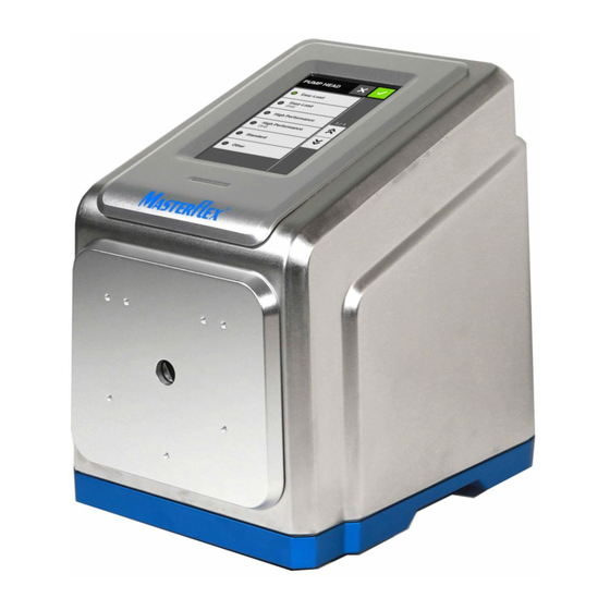
Section 2: Basic Setup & Settings SECTION 2: BASIC SETUP & SETTINGS Touchscreen Active Light Pump Head Mounting Holes Ethernet Port USB Port Profibus Fuse Power Switch Power Cord 31-Pin Open Head Sensor ® ® Masterflex Masterflex MasterSense™ Process Drives... -
Page 8: Touchscreen Icons
Close/Cancel Ramp Down Confirm Ramp Up Connectivity Status Record Volume Continuous Mode Reset Counterclockwise Screen Lock Delete Settings Display Brightness Start Edit Stop Language Time Mode Logout Update Available New Program Volume Mode ® ® Masterflex Masterflex MasterSense™ Process Drives... -
Page 9: Before Starting The Drive
After 30 minutes of inactivity the I/P will enter sleep mode and the display will turn off . Tapping the touchscreen will reactivate the drive. To enable (default) or disable the screen saver see "Screen Saver" on page 2-6. ® ® Masterflex Masterflex MasterSense™ Process Drives... -
Page 10: Settings
5. Tap MM to select minutes and enter the desired time using the onscreen keypad. 6. If using 12-HOUR time, tap AM/PM to select either AM or PM. 7. Tap CONFIRM to save or CANCEL to discard changes. ® ® Masterflex Masterflex MasterSense™ Process Drives... -
Page 11: Setting The Date
Select the desired current or voltage operating range from the available list. c. Tap CONFIRM to save or CANCEL to discard changes. Th e Analog Output Screen will be displayed. 5. Tap CONFIRM ® ® Masterflex Masterflex MasterSense™ Process Drives... -
Page 12: Device Information
3. Tap DEVICE NAME. Th e Device Name Screen will be displayed. 4. Enter the desired pump name using the onscreen keypad (up to 8 characters). 5. Tap CONFIRM to save or CANCEL to discard changes. ® ® Masterflex Masterflex MasterSense™ Process Drives... -
Page 13: Wi-Fi Settings
3. Tap ETHERNET SETTINGS. Th e Ethernet Settings Screen will be displayed. 4. Tap DHCP to automatically confi gure IP settings or STATIC to manually edit settings using the onscreen keypad. 5. Tap CONFIRM to save or CANCEL to discard changes. ® ® Masterflex Masterflex MasterSense™ Process Drives... -
Page 14: User Management
8. Tap the required PERMISSION LEVEL. NOTE: Th ere must always be at least one ADMIN user. 9. Tap CONFIRM to save or CANCEL to discard any changes. ® ® Masterflex Masterflex MasterSense™ Process Drives... -
Page 15: Pump Head Selection
2. Select the desired tube size from the list of available options. NOTE: Only tube sizes compatible with the selected pump head will be displayed. 3. Tap CONFIRM to save or CANCEL to discard changes and return to the mode run screen. ® ® Masterflex Masterflex MasterSense™ Process Drives... -
Page 16: Auto Start
Management" on page 2-8). 5. Navigate to the Continuous, Time or Volume Mode screens. 6. Press and hold PRIME until there are no bubbles visible in the tubing. Priming will stop when PRIME is released. ® ® Masterflex 2-10 Masterflex MasterSense™ Process Drives... -
Page 17: Tube Calibration
(For further information see "User Management" on page 2-8). 4. Navigate to the Continuous, Time or Volume Mode screens. 5. Tap DIRECTION to select either clockwise or counterclockwise fl ow direction. ® ® Masterflex 2-11 Masterflex MasterSense™ Process Drives... - Page 18 Th e best results are obtained after tubing has been run in the pump for approximately 20-30 minutes. • Steps 9–14 can be repeated as necessary to optimize the accuracy of the tubing calibration. ® ® Masterflex 2-12 Masterflex MasterSense™ Process Drives...
-
Page 19: Section 3: Operation
Selection Screen can be accessed from any of the mode screens by tapping the MODE NAME BANNER. Return to Previous Screen Continuous Mode Time Mode Volume Mode Analog Input Mode Page Scroll Add New Program Settings Tap the desired mode or program to access individual mode or program screens. ® ® Masterflex Masterflex MasterSense™ Process Drives... -
Page 20: Continuous Mode
I. SCREEN LOCK: Locking the screen disables all touchscreen functions. To lock the screen: Press and hold UNLOCKED until the icon changes to LOCKED and a red border appears around the screen. To unlock the screen: Press and hold LOCKED until the icon changes to UNLOCKED ® ® Masterflex Masterflex MasterSense™ Process Drives... -
Page 21: Continuous Mode Operation
. Th e drive will commence operation at the fl ow rate and direction shown. 8. Tap STOP when the drive operation is no longer required. NOTE: In Continuous Mode the drive will continue to operate at the displayed fl ow rate and direction until stopped. ® ® Masterflex Masterflex MasterSense™ Process Drives... -
Page 22: Saving Continuous Mode Settings As A New Program
6. Tap CONFIRM to save or DELETE to cancel. NOTE: • Once saved, new programs are added in alphabetical order to the bottom of the Mode Selection Screen. • If there are multiple programs tapping SCROLL will display additional pages. ® ® Masterflex Masterflex MasterSense™ Process Drives... -
Page 23: Time Mode
J. PRIME: Press and hold to prime the pump drive (for further information see "Priming the Pump Drive" on page 2-10). K. START/STOP/PAUSE: During operation, the display will change from START to PAUSE STOP/ RESET ® ® Masterflex Masterflex MasterSense™ Process Drives... -
Page 24: Time Mode Edit Screen
Time Mode Edit Screen (for further information see "Tube Calibration" on page 2-11). • If required, prime the pump before operation (for further information see "Priming the Pump Drive" on page 2-10). ® ® Masterflex Masterflex MasterSense™ Process Drives... - Page 25 11. If required, adjustments can be made to any of the Time Mode option settings during operation. To make any adjustments: a. Tap PAUSE and then repeat steps 2–9 above. b. Tap CONTINUE to complete the pump operation once the desired changes have been made. ® ® Masterflex Masterflex MasterSense™ Process Drives...
-
Page 26: Saving Time Mode Settings As A New Program
6. Tap CONFIRM to save or DELETE to cancel. NOTE: • Once saved, new programs are added in alphabetical order to the bottom of the Mode Selection Screen. • If there are multiple programs tapping SCROLL will display additional pages. ® ® Masterflex Masterflex MasterSense™ Process Drives... -
Page 27: Volume Mode
I. FLOW RATE: Displays the current fl ow rate in the unit of measurement selected by the user. J. PRIME: Press and hold to prime the pump drive (for further information see "Priming the Pump Drive" on page 2-10). ® ® Masterflex Masterflex MasterSense™ Process Drives... -
Page 28: Volume Mode Edit Screen
Management" on page 2-8). Th e touchscreen display will revert to the previously used operation mode. • Confi rm that the tubing has been calibrated by checking that Calibration Complete is displayed on the Volume Mode Edit Screen (for further information see "Tube Calibration" on page 2-11). ® ® Masterflex 3-10 Masterflex MasterSense™ Process Drives... - Page 29 Volume Mode Edit Screen. 8. If required, tap ANTI-DRIP. Th e Anti-Drip Screen will be displayed (for further information see "Anti- Drip" on page 3-12). ® ® Masterflex 3-11 Masterflex MasterSense™ Process Drives...
-
Page 30: Anti-Drip
Tap FLOW to enter the desired fl ow rate using the onscreen keypad. b. Tap UNITS to enter the desired fl ow rate units using the onscreen keypad. c. Tap CONFIRM to save changes and return to the Record Dispense Screen. ® ® Masterflex 3-12 Masterflex MasterSense™ Process Drives... -
Page 31: Analog Input Mode
Th e Analog Input Mode Run Screen is accessed by selecting ANALOG INPUT from the Mode Selection Screen. A. Mode Name Banner B. Prime C. Start/Stop D. Flow Direction E. Screen Lock F. Logout ® ® Masterflex 3-13 Masterflex MasterSense™ Process Drives... -
Page 32: Analog Input
If required, prime the pump before operation (for further information see "Priming the Pump Drive" on page 2-10). • Confi rm that the pump drive is connected to the appropriate equipment through the drive’s 31-Pin female connection port. ® ® Masterflex 3-14 Masterflex MasterSense™ Process Drives... -
Page 33: Saving Analog Input Mode Settings As A New Program
6. Tap CONFIRM to save or DELETE to cancel. NOTE: • Once saved, new programs are added in alphabetical order to the bottom of the Mode Selection Screen. • If there are multiple programs tapping SCROLL will display additional pages. ® ® Masterflex 3-15 Masterflex MasterSense™ Process Drives... -
Page 34: Masterflexlive
7. Tap CONFIRM to save or DELETE to discard changes. NOTE: • Once saved, new programs are added in alphabetical order to the bottom of the Mode Selection Screen. • If there are multiple programs tapping SCROLL will display additional pages. ® ® Masterflex 3-16 Masterflex MasterSense™ Process Drives... -
Page 35: Adding A New Program: Time Mode
INFINITE ∞ to select an infi nite number of dispense cycles. If infi nite is selected, the pump will run continuously. b. Tap CONFIRM to save or CANCEL to discard changes and return to the Time New Pro- gram Screen. 10. Tap CONFIRM to save or DELETE to discard changes. NOTE: ® ® Masterflex 3-17 Masterflex MasterSense™ Process Drives... -
Page 36: Adding A New Program: Volume Mode
8. Tap DIRECTION to select either clockwise or counterclockwise fl ow direction. 9. Tap BATCH TOTAL to adjust the number of dispenses in each batch cycle. Th e Batch Total Screen will ® ® Masterflex 3-18 Masterflex MasterSense™ Process Drives... -
Page 37: Adding A New Program: Analog Input Mode
Analog Input New Program Screen. 8. Tap DIRECTION to select either clockwise or counterclockwise fl ow direction. 9. Tap CONFIRM to save or DELETE to discard changes. ® ® Masterflex 3-19 Masterflex MasterSense™ Process Drives... -
Page 38: Using Program Modes
2. Edit the settings for the selected mode as desired. For instructions on editing individual mode settings see: • "Adding a New Program: Continuous Mode" on page 3-16. • "Adding a New Program: Time Mode" on page 3-16. • "Adding a New Program: Volume Mode" on page 3-18. ® ® Masterflex 3-20 Masterflex MasterSense™ Process Drives... -
Page 39: Deleting A Program
Th e Program Edit Screen will be displayed. 2. Tap DELETE PROGRAM 3. Tap DELETE to delete the program and return to the Mode Selection Screen or CANCEL to return to the previous screen. ® ® Masterflex 3-21 Masterflex MasterSense™ Process Drives... -
Page 40: Section 4: Communication Specification
IP address is within the subnet mask range of the PLC and the pump. Th e default addressing methods for the pump is DHCP. Static IP address may be assigned through the Ethernet settings menu. ® ® Masterflex Masterflex MasterSense™ Process Drives... - Page 41 Section 4: Communication Specification In the device menu, enable the Ethernet/IP feature by toggling to select ON. Once enable, the following message appears on the UI. Press Accept on this screen. ® ® Masterflex Masterflex MasterSense™ Process Drives...
- Page 42 -Th e bit changes state from local to remote on a 1 to 0 transition. -Once enabled, the Ethernet/IP banner will appear at the top of the pump screen. Shows Ethernet/IP active in volume Dispense Mode ® ® Masterflex Masterflex MasterSense™ Process Drives...
-
Page 43: Masterflex Ethernet/Ip
Section 4: Communication Specification MASTERFLEX ETHERNET/IP Input data; 56 bytes of input data from pump to master. Bytes Data Type Description 32-Bit INT Pump Status Bit 0: Status OK Bit 1: Pump Running Bit 2: Dispense Running Bit 3: Tube Uncalibrated... - Page 44 32- bit INT Set Batch Count Total (0 = infinite) Masterfl ex Flow Units Correlation Table Index 650 RPM I/P mL/min mL/hr L/min L/hr L/day uL/min uL/hr gal/min gal/hr gal/day oz/min oz/hr cum/hr ® ® Masterflex Masterflex MasterSense™ Process Drives...
-
Page 45: Profibus
Once that fi eld is selected you now enter the PROFIBUS SETTINGS screen. Here you can assign the Profi bus address to be a value (in between 1 and 126). Th e default Profi bus address is 7. ® ® Masterflex Masterflex MasterSense™ Process Drives... - Page 46 Section 4: Communication Specification Ensure the pump and the PLC user interface are confi gured for the same address and confi rm by pressing the green check mark at the top of the screen ® ® Masterflex Masterflex MasterSense™ Process Drives...
-
Page 47: Profibus Data
Section 4: Communication Specification PROFIBUS DATA Th e MASTERFLEX Pump Drive operates as a DP-V0 Slave. GSD File: CPMP0FF8.GSD ID Number: 0FF8 HEX Default Slave Address: 7 Cyclic Input Data: 56 bytes Cyclic Output Data: 28 bytes Table 1 below lists the 56 bytes of cyclic input data, from pump to master. - Page 48 Pump Control, a 4-byte unsigned integer as shown in Table 3 above, controls the pump’s operation in separate bits. See Table 4 below for the description of each bit in Pump Control. ® ® Masterflex Masterflex MasterSense™ Process Drives...
- Page 49 Set Dispense On Seconds is the amount of time the pump will dispense in Time Dispense Mode. Set Dispense Off Seconds is used for both Time and Volume dispense modes. It sets the amount of time the pump will pause between dispenses. ® ® Masterflex 4-10 Masterflex MasterSense™ Process Drives...
-
Page 50: Section 5: Service & Maintenance
Th e Settings Screen will be displayed. 2. SCROLL through the Settings Screen pages to locate DEVICE INFORMATION. 3. Tap DEVICE INFORMATION. 4. Tap FACTORY RESET and follow the onscreen prompts. ® ® Masterflex Masterflex MasterSense™ Process Drives... -
Page 51: Cleaning The Pump Drive
I/P Process Drive: Description Part Number Footswitch (NEMA)* 07575-84 Interface Cable DB9M/DB9F 22050-54 Cable USB Type A/Type B M/M 22050-60 REPLACEMENT PARTS Description Part Number Fuse-T6.3 A, 5 x 20 mm B-1115-0054 ® ® Masterflex Masterflex MasterSense™ Process Drives... -
Page 52: Troubleshooting
Touchscreen unrespon- Wearing thick latex Remove gloves before using the touchscreen. NOTE: Consult sive. gloves can make the your company or laboratory safety guidelines before removing screen less responsive. any personal protective equipment. ® ® Masterflex Masterflex MasterSense™ Process Drives... -
Page 53: Error Definitions
Error #9: Over Speed Description: The drive has exceeded commanded speed value. Actions: Drive will stop immediately. Verify load is correct and power cycle the pump drive. If error persists see "Technical Assistance" on page 5-8. ® ® Masterflex Masterflex MasterSense™ Process Drives... -
Page 54: 31-Pin Electrical Connections
Remote Start/Stop, CW/CCW, Prime Grnd Ref. General Alarm Relay Output (N.O.) Speed Signal Output Ground Reference Not Used Tach Ground Reference Local/RemoteRelay Output (N.O.) Motor Running Relay Output (N.O.) 23–31 Not Used Tach Output (Open Collector) ® ® Masterflex Masterflex MasterSense™ Process Drives... -
Page 55: Specifications
RJ45 Ethernet USB, Type A (5 VDC @ 0.5 A) CONSTRUCTION Dimensions (L x W x H): 12.88” x 10.25” x 13.65” (327 mm x 260 mm x 346 mm) Weight: 48 lbs. (21.77kg) ® ® Masterflex Masterflex MasterSense™ Process Drives... - Page 56 Exposed material is stainless steel, aluminum, thermoplastic COMPLIANCE All Models UL 61010-1, UL 61010-2-081 US/CAN For CE mark: EN61010-1, Low Voltage Directive ETSI EN 301 489-1, EMC Directive EN IEC 63000, RoHS Directive Pump Head EN809, Machinery Directive ® ® Masterflex Masterflex MasterSense™ Process Drives...
-
Page 57: Technical Assistance
Once the useful life of the product has ended, please ensure proper disposal according to local laws. Plastic and electronic components should be disposed of at a recycling facility. Please refer to local regulations regarding proper disposal. ® ® Masterflex Masterflex MasterSense™ Process Drives... - Page 58 *EN809 manufactured by: US & Canada only Masterflex LLC Toll Free 1-800-MASTERFLEX | 1-800-637-3739 28092 W Commercial Avenue, Barrington, IL 60010 Outside US & Canada tmasterflex.tech@avantorsciences.com www.avantorsciences.com/masterflex 1-847-381-7050...
Need help?
Do you have a question about the I/P MASTERSENSE MFLX77421-00 and is the answer not in the manual?
Questions and answers