Table of Contents
Advertisement
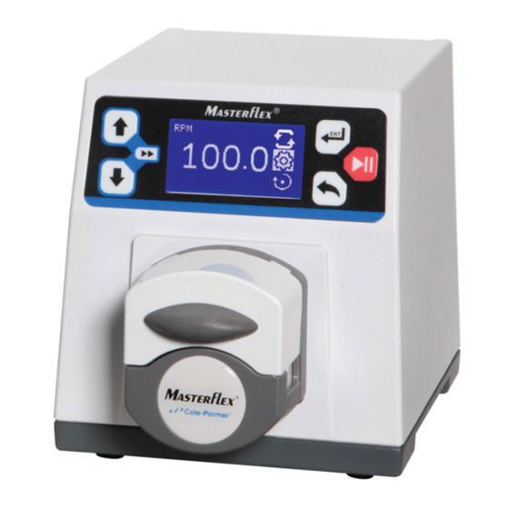
MASTERFLEX® 77123-00 and 07525-20
®
(US & Canada only) Toll Free 1800MASTERFLEX • 18006373739
(Outside US & Canada) 18475497600 • 18473817050
www.masterflex.com • techinfo@masterflex.com
®
OPERATING MANUAL:
DIGITAL PUMP
DRIVES
Model Nos.
07525-20
07525-40
77123-00
®
A12997328
Edition 03
Advertisement
Table of Contents

Related Manuals for Masterflex L/S 07525-20


Summary of Contents for Masterflex L/S 07525-20
- Page 1 ® ® OPERATING MANUAL: DIGITAL PUMP DRIVES Model Nos. 07525-20 07525-40 77123-00 MASTERFLEX® 77123-00 and 07525-20 A12997328 Edition 03 ® (US & Canada only) Toll Free 1800MASTERFLEX • 18006373739 (Outside US & Canada) 18475497600 • 18473817050 www.masterflex.com • techinfo@masterflex.com...
- Page 2 © 2019 Cole-Parmer Instrument Company. All rights reserved. Masterflex – Reg TM Cole-Parmer Instrument Company. Trademarks bearing the symbol in this publication are registered in the U.S. and in other countries. ® PUMP FOR LIQUIDS ORIGINAL INSTRUCTIONS MASTERFLEX ® Digital Pump Drive Operating Manual...
- Page 3 When using hazardous chemical and biological agents, take all suit- able protective measures, such as wearing protective glasses and gloves resistant to the substances used. Follow local and/or national regulations for safe operation and maintenance of the system. Masterflex MASTERFLEX ® Digital Pump Drive Operating Manual...
- Page 4 ATEX or the NEC (National Electrical Code); including, but not limited to use with flammable liquids. Consult the factory for products suitable for these types of applications MASTERFLEX ® Digital Pump Drive Operating Manual Masterflex...
-
Page 5: Table Of Contents
Global Options Menu ......... .3-38 Masterflex MASTERFLEX ®... - Page 6 Technical Assistance ..........8-2 MASTERFLEX ®...
- Page 7 Set Off Time Menu Screens ........3-38 Masterflex MASTERFLEX ®...
- Page 9 Continuous Mode Operation ........3-30 Masterflex MASTERFLEX ®...
-
Page 11: Introduction
Introduction Section 1 The Digital drive controls the speed of MASTERFLEX® Pump Heads to provide flow rates from 0.00013 to 324 mL/min. Application Solutions Advantages of Peristaltic Pumps: • No seals in contact with the medium pumped. • No valves to clog. -
Page 12: General Description
In addition to high accuracy, precision, repeatability and resolution of speed (or flow rate), the MASTERFLEX drive features an intuitive, man/machine interface with a four-line graphical LCD display providing direct readout of pump speed (rpm), flow rate (user-selected units), number of dispenses, and menu options. -
Page 13: Installation And Setup
If you use the pump drive in another country, you must use a power cord set that meets the requirements of that country. DANGER: High voltages exist and are accessible. Use extreme caution when servicing internal components. Masterflex MASTERFLEX ® Digital Pump Drive Operating Manual... - Page 14 (continued) protective glasses and gloves resistant to the substances used. Follow local and/or national regulations for safe operation and maintenance of the system. MASTERFLEX ® Digital Pump Drive Operating Manual Masterflex...
-
Page 15: Operation
CAUTION: Power must be turned off before connecting the exter- nal remote control cable to prevent damage to the drive. WARNING: Tubing breakage may result in fluid being sprayed from pump. Use appropriate measures to protect operator and equipment. Masterflex MASTERFLEX ® Digital Pump Drive Operating Manual... -
Page 16: Control Panel
While the keys are pressed, these keys operate the drive at the maximum allowed speed/flow rate and in the direction shown on the display. When released, the drive returns to its original speed or flow rate. MASTERFLEX ® Digital Pump Drive Operating Manual Masterflex... -
Page 17: Priming The Pump
Priming will stop when keys are released. CAUTION: Keep fingers away from rotor while pump is in operation. Stop pump before loading or unloading tubing. Masterflex MASTERFLEX ® Digital Pump Drive Operating Manual... -
Page 18: Main Screen
) to allow for continuous dispense cycling. Refer to Copy Dispense Mode in this manual. SETTINGS Mode settings menu. PUMP DIRECTION Select the direction of the pump flow. The icon will rotate when the pump is running. MASTERFLEX ® Digital Pump Drive Operating Manual Masterflex... -
Page 19: Continuous Mode Screen
. The digits can be navigated individually using the arrows; switch between digits by using the key. After selecting an optimal flow rate, press again to validate. Press key to exit. Masterflex MASTERFLEX ® Digital Pump Drive Operating Manual... - Page 20 : Informative only. This icon will display when the I. Keypad Lockout keypad lockout is turned on in the setting menu. Locking the keypad will prevent someone from changing the settings on the drive. MASTERFLEX ® Digital Pump Drive Operating Manual Masterflex...
-
Page 21: Settings Menu
Flow Unit selection screen. NOTE: When switching to Copy Dispense Mode, flow rate adjustments are displayed in RPM only. Figure 3-4. Flow Unit Selection Screens. Masterflex MASTERFLEX ® Digital Pump Drive Operating Manual... - Page 22 Tubing Size: and its Maximum Flow Rate are displayed. Select desired tubing size by using the UP/DOWN keys to highlight the size tubing (continued) installed in the pump head and press ENTER. Figure 3-5. Tubing Size Selection Screens. MASTERFLEX ® Digital Pump Drive Operating Manual Masterflex...
- Page 23 PLEASE NOTE that the preset values assume the pump is dispensing water with no back pressure. Every batch of tubing can have a slight variation in ID and wall thickness. MASTERFLEX® tubing is manufactured to tight tolerances and is required for warranty and provides optimal pumping performance and accuracy.
- Page 24 Clear the tubing calibration and re-calibrate using a larger dispense amount. 9. Clear the tubing calibration by using the UP/DOWN keys to highlight the delete icon and press ENTER. 3-10 MASTERFLEX ® Digital Pump Drive Operating Manual Masterflex...
-
Page 25: Global Options Menu
See Remote Control. SOUNDS: Select a beep for keypad, end of dispenses, and batches. See Sounds. KEYPAD LOCKOUT: Allows for the keypad to be locked and unlocked. See Keypad Lockout. Masterflex MASTERFLEX ® Digital Pump Drive Operating Manual 3-11... - Page 26 AUTOSTART: Allows the drive to restart when power is applied. By default the drive will not restart when power is applied. See Autostart. DEFAULT SETTINGS: Allows the drive to be reset to factory settings. See Default Settings. 3-12 MASTERFLEX ® Digital Pump Drive Operating Manual Masterflex...
-
Page 27: Remote Control Menu
By default the input is deactivated Using the UP and DOWN arrows on the control panel, highlight the icon to activate, and press ENTER. A check mark will move next to it. Masterflex MASTERFLEX ® Digital Pump Drive Operating Manual 3-13... - Page 28 CONTINUOUS PUMP MODE screen appears. The Voltage input icon will be displayed. NOTE: When Voltage Input is selected the drive will not start until the VOLTAGE INPUT is ON and in CONTINUOUS PUMP MODE. 3-14 MASTERFLEX ® Digital Pump Drive Operating Manual Masterflex...
-
Page 29: Remote Control Voltage Output Menu
Using the UP and DOWN arrows on the control panel, highlight the icon to activate, and press ENTER. A check mark will move next to it. Masterflex MASTERFLEX ® Digital Pump Drive Operating Manual 3-15... - Page 30 VOLTAGE OUTPUT is ON and in CONTINUOUS PUMP MODE. NOTE: The Voltage Output indicates the Running Command Speed. Use the Motor Running relay (normally open) to indicate if pump is running. 3-16 MASTERFLEX ® Digital Pump Drive Operating Manual Masterflex...
-
Page 31: Remote Control Current Input Menu
Using the UP and DOWN arrows on the control panel, highlight the icon to activate, and press ENTER. A check mark will move next to it. Masterflex MASTERFLEX ® Digital Pump Drive Operating Manual 3-17... - Page 32 CONTINUOUS PUMP MODE screen appears. The Current input icon will be displayed. NOTE: When Current Input is selected the drive will not start until the CURRENT INPUT is ON and in CONTINUOUS PUMP MODE. 3-18 MASTERFLEX ® Digital Pump Drive Operating Manual Masterflex...
-
Page 33: Remote Control Current Output Menu
Using the UP and DOWN arrows on the control panel, highlight the icon to activate, and press ENTER. A check mark will move next to it. Masterflex MASTERFLEX ® Digital Pump Drive Operating Manual 3-19... - Page 34 CURRENT OUTPUT is ON and is in CONTINUOUS PUMP MODE. NOTE: The Current Output indicates the Running Command Speed. Use the Motor Running contacts (normally open) to indicate if pump is running. 3-20 MASTERFLEX ® Digital Pump Drive Operating Manuall Masterflex...
-
Page 35: Pin Configuration With Wiring Scheme
NOTE: Open collector outputs in "low impedance" state are at earth ground and when in "high impedance" state are essentially floating. See Open Collector page 3-24. Masterflex MASTERFLEX ® Digital Pump Drive Operating Manual... -
Page 36: Remote Control Inputs And Outputs
Normally Open, closed when an alarm is displayed. Output Relay: Local/Remote Indicator Normally Open, closed when in remote control Relay: mode (Voltage Input or Current Input). 24V DC Aux. Output: 24V DC @ 0.200A 3-22 MASTERFLEX ® Digital Pump Drive Operating Manual Masterflex... - Page 37 Voltage or Current input. Enabling this will turn ON the last known input (Voltage or Current) that had been activated from the Remote control menu and saved. Masterflex MASTERFLEX ® Digital Pump Drive Operating Manual...
-
Page 38: Open Collector Output
NOTE: when using the 24V supply on the interface connector, current draw must be limited to 150 mA. NOTE: DO NOT connect 120V supply lines to open collector outputs! Figure 3-11. Terminating Open Collector Output to a PLC. 3-24 MASTERFLEX ® Digital Pump Drive Operating Manual Masterflex... -
Page 39: Sound Menu
By default the sound is deactivated, using the UP and DOWN arrows on the control panel, highlight the icon to activate, press ENTER. A check mark will move next to it. Masterflex MASTERFLEX ® Digital Pump Drive Operating Manual 3-25... - Page 40 After activating or deactivating sounds, save the sound settings by going to the Batch Sound setting screen and highlighting the save icon at the bottom and pressing ENTER. 3-26 MASTERFLEX ® Digital Pump Drive Operating Manual Masterflex...
-
Page 41: Keypad Lockout Menu
UP and DOWN arrows on the control panel, highlight the icon to activate and press ENTER. A check mark will move next to it. The START/STOP key will still function. Masterflex MASTERFLEX ® Digital Pump Drive Operating Manual... -
Page 42: Display Contrast Menu
By default the display is set for optimum viewing, using the UP and DOWN arrows on the control panel, highlight icon to increase the contrast or icon to decrease the contrast, then press ENTER. 3-28 MASTERFLEX ® Digital Pump Drive Operating Manual Masterflex... -
Page 43: Autostart Menu
By default the output is deactivated Using the UP and DOWN arrows on the control panel, highlight the icon to activate and press ENTER. A check mark will move next to it. Masterflex MASTERFLEX ® Digital Pump Drive Operating Manual 3-29... - Page 44 Stopped from Front panel Not running Not running Not running NOTE: In Continuous Mode when using the START/STOP input the drive is started with a closed contact and stopped when the contacts are opened. 3-30 MASTERFLEX ® Digital Pump Drive Operating Manual Masterflex...
-
Page 45: Default Settings Menu
DEFAULT SETTINGS: This allows the user to restore the drive back to the factory settings. Highlight the icon and press ENTER to restore factory settings or icon or BACK key to cancel. Masterflex MASTERFLEX ® Digital Pump Drive Operating Manual 3-31... -
Page 46: Copy Mode Screen
Locking the keypad will prevent someone from changing the settings on the drive. : Informative only. This icon will only display when I. Off Time Icon an Off Time is set. 3-32 MASTERFLEX ® Digital Pump Drive Operating Manual Masterflex... -
Page 47: Settings Menu
UP/DOWN or ENTER key to select the SETTINGS icon from the Mode Operation screen. 2. Navigating the SETTINGS Menu: Use the UP/DOWN or the ENTER key to select desired setting. Masterflex MASTERFLEX ® Digital Pump Drive Operating Manual 3-33... -
Page 48: Copy Flow Rate Menu
ENTER key. After selecting an optimal flow rate, press ENTER again to validate. Press the back key to exit edit mode and save. (NOTE: RPM is the only unit available in Copy Mode.) 3-34 MASTERFLEX ® Digital Pump Drive Operating Manual Masterflex... -
Page 49: Set Copy Menu
SET COPY: Press the START/RUN key on the control panel initiate copy. Once the amount of desired fluid is dispensed, press the STOP/PAUSE key SAVE COPY : Pressing the ENTER key with this icon highlighted will save the copy. Masterflex MASTERFLEX ® Digital Pump Drive Operating Manual 3-35... -
Page 50: Set Batch Count Menu
: Pressing the ENTER key with this icon highlighted will delete the copy. Set Batch Count Menu Figure 3-20. Set Batch Count Menu Screens. NAVIGATION: From the SETTINGS MENU select the Batch Count screen, shown above, and press ENTER. 3-36 MASTERFLEX ® Digital Pump Drive Operating Manual Masterflex... - Page 51 0000 will allow for continuous dispense cycling. This will also change the display icon to infinity ( Press the back key to exit. To reset the batch count, highlight the lower left and press ENTER. Masterflex MASTERFLEX ® Digital Pump Drive Operating Manual...
-
Page 52: Off Time Menu
NOTE: Setting it to 00:00:00 will require the START/STOP button on the control panel to initiate each copy. Global Options Menu NAVIGATION: From the SETTINGS MENU select the Global Options Menu screen, shown above, and press ENTER. See Global Options Menu. 3-38 MASTERFLEX ® Digital Pump Drive Operating Manual Masterflex... -
Page 53: Maintenance
Replacement Miniflex Dual Channel Pump Head 77220-30 Replacement Microflex Single Channel Pump Head 77123-80 Cleaning Keep the drive enclosure clean with mild detergents. Do not immerse or use excessive fluid when cleaning. Masterflex MASTERFLEX ® Digital Pump Drive Operating Manual... -
Page 55: Troubleshooting
Main Menu or Setup Menu and verify settings. 4. Return to Mode screen and verify icon shows. Remote Control Mode. 5. See Remote Control Mode in this manual for further details. Masterflex MASTERFLEX ® Digital Pump Drive Operating Manual... -
Page 56: Error Definitions
The drive has exceeded commanded speed value. Error Condition(s): The motor has exceeded the commanded speed value by 20%. Actions: Drive will stop immediately. Verify load is correct and power cycle drive. If error persists consult factory. MASTERFLEX ® Digital Pump Drive Operating Manual Masterflex... - Page 57 Error Condition(s): 1) Checksum value in EEPROM does not match calculated value. 2) Data in EEPROM is out of range. Actions: Error will be cleared after 10 seconds and parameters will be reset to default values. If error persists consult factory. Masterflex MASTERFLEX ® Digital Pump Drive Operating Manual...
-
Page 59: Accessories
Connector DB-25 male; connector only; use to create own cable 07523-94 Cable assembly, DB-25 male connector and 07523-95 25-ft (7.9m) cable w/stripped wire ends Dispensing Wand with 6 ft. (1.8m) cable 07523-97 and DB-25 male connector Masterflex MASTERFLEX ® Digital Pump Drive Operating Manual... -
Page 61: Specifications
Remote Inputs: STOP/START, CW/CCW, PRIME CURRENT/VOLTAGE ENABLE (Contact closure) Voltage input (0–10V DC @ 10 k ±50V common mode range Current input (0–20 mA or 4–20mA @ 250 ±50V common mode range Masterflex MASTERFLEX ® Digital Pump Drive Operating Manual... - Page 62 IEC320 C14 AC Inlet with an input range of 90V AC to 264V AC @ 47-63 Hz, 90W. Output: Plug 2.5 mm x 5.5 mm, Center Positive 24V DC Compliance: PFC, cUL, UL, TUV, BSMI, CCC, PSE, FCC, CE MASTERFLEX ® Digital Pump Drive Operating Manual Masterflex...
-
Page 63: Warranty
Warranty, Product Return and Section 8 Technical Assistance Warranty Use only MASTERFLEX precision tubing with MASTERFLEX pumps to ensure optimum performance. Use of other tubing may void applicable warranties. This product is warranted against defects in material or workmanship, and... -
Page 64: Product Return
Any damages resulting from improper packaging are your responsibility. Technical Assistance If you have any questions about the use of this product, contact the Manufacturer or authorized seller. MASTERFLEX ® Digital Pump Drive Operating Manual Masterflex... - Page 66 ® US & Canada only *EN809 manufactured by: Toll Free 1-800-MASTERFLEX | 1-800-637-3739 Cole-Parmer Instrument Company Outside US & Canada 28W092 Commercial Avenue, Barrington, IL 60010 1-847-549-7600 | 1-847-381-7050 techinfo@masterflex.com | www.masterflex.com...
Need help?
Do you have a question about the L/S 07525-20 and is the answer not in the manual?
Questions and answers