
Related Manuals for Advantech UNO-3283G


Summary of Contents for Advantech UNO-3283G
- Page 1 User Manual UNO-3200G Series 電腦 Intel® 6th Gen. Core Processors Embedded Automation PC, with 2 or 4 PCIe/ PCI Extension Slots...
- Page 2 No part of this manual may be reproduced, copied, translated or transmitted in any form or by any means without the prior written permission of Advantech Co., Ltd. Information provided in this manual is intended to be accurate and reliable. How- ever, Advantech Co., Ltd.
- Page 3 *Part number: UNO-3283G- UNO-3283G- UNO-3283G- UNO-3285G- UNO-3285G- UNO-3285G- 674AE 654AE 634AE 674AE 654AE 634AE UNO3283G674 UNO3283G654 UNO3283G634 UNO3285G674 UNO3285G65 UNO3285G634 1601E-T 1601E-T 1601E-T 1601E-T 41601E-T 1601E-T UNO3283G674 UNO3283G654 UNO3283G634 UNO3285G674 UNO3285G65 UNO3285G634 1602E-T 1602E-T 1602E-T 1602E-T 41602E-T 1602E-T UNO3283G674 UNO3283G654...
- Page 4 Because of Advantech’s high quality-control standards and rigorous testing, most of our customers never need to use our repair service. If an Advantech product is defec- tive, it will be repaired or replaced at no charge during the warranty period. For out- of-warranty repairs, you will be billed according to the cost of replacement materials, service time and freight.
- Page 5 Technical Support and Assistance Visit the Advantech web site at http://support.advantech.com where you can find the latest information about the product. Contact your distributor, sales representative, or Advantech's customer service center for technical support if you need additional assistance. Please have the following information ready before you call: –...
- Page 6 Caution: The earthing wire of the protective bonding conductor shall be green-and- yellow, 18AWG/0.75mm2 minimum. DISCLAIMER: This set of instructions is given according to IEC 704-1. Advantech disclaims all responsibility for the accuracy of any statements contained herein. UNO-3200G Series User Manual...
- Page 7 安全指示 請仔細閱讀此安全操作說明。 請妥善保存此用戶手冊供日後參考。 用濕抹布清洗設備前,請確認拔除電源線。請勿使用液體或去污噴霧劑清洗設 備。 對於使用電源線的設備,設備周圍必須有容易接觸到的電源插座。 請勿在潮濕環境中試用設備。 請在安裝前確保設備放置在可靠的平面上,意外摔落可能會導致設備損壞。 設備機殼的開孔適用於空氣對,從而防止設備過熱。請勿覆蓋開孔。 當您連接設備到電源插座前,請確認電源插座的電壓符合要求。 請將電源線佈置在人們不易絆倒的位置,請勿在電源線上覆蓋任何雜物。 請注意設備上所有的警告標示。 如果長時間不使用設備,請拔除與電源插座的連結,避免設備被超標的電壓波動 損壞。 請勿讓任何液體流入通風口,以免引起火灾或短路。 請勿自行打開設備。為了確保您的安全,請透過經認證的工程師來打開設備。 如遇下列情况,請由專業人員維修: 電源線或插頭損壞; 設備內部有液體流入; 設備曾暴露在過度潮濕環境中使用; 設備無法正常工作,或您無法透過用戶手冊來正常工作; 設備摔落或損壞; 設備有明顯外觀損; 請勿將設備放置在超出建議溫度範圍的環境,即不要低於 ‐20 ℃ (‐4 ℉) 或高於 60 (140 ℉) ,否則可能會造成設備損壞。 ℃ 注意:若電池更換不正確,將有爆炸危險。因此,只可以使用製造商推薦的同一...
- Page 8 RoHS Claim 設備名稱:電腦 型號 (型式) :UNO-3283G、UNO-3285G ( 系列型號請參見手冊載明型號) Equipment name Type designation (Type) 限用物質及其化學符號 Restricted substances and its chemical symbols 多溴聯苯 六價鉻 多溴二苯醚 Polybromina 單元 Unit 鎘 Hexavalent Polybrominate 鉛 Lead 汞 Mercury Cadmium chromium d diphenyl (Pb) (Hg) (Cd)
-
Page 9: Table Of Contents
Accessories....................6 Chapter Hardware Functionality.......7 Introduction ....................8 Figure 2.1 UNO-3283G Front View ..........8 Figure 2.2 UNO-3285G Front View ..........8 Serial Interface (COM1/COM2)..............9 Figure 2.3 Serial Interface (COM1, COM2) ......... 9 2.2.1 RS-232/422/485 Interface (COM1 & COM2) ........ 9 2.2.2... - Page 10 Mounting UNO-3200G Series ..............24 Figure 3.2 Stand Mount ............. 24 Figure 3.3 Enclosure Mount ............24 Figure 3.4 Wall Mount (01) ............25 Figure 3.5 Wall Mount (02) ............25 Appendix A System Settings and Pin Assignments System I/O Address and Interrupt Assignment........28 Table A.1: Interrupt Assignments ..........
-
Page 11: Chapter 1 Overview
Chapter Overview This chapter provides an overview of UNO-3200G series' specifica- tions. Sections include: Introduction Hardware specification Safety precautions Chassis dimensions Accessories... -
Page 12: Introduction
CE, FCC, UL, CCC, BSMI Dimensions (W×D×H): – UNO-3283G: 142 x 238 x 177 mm (5.6'' x 9.3'' x 6.9'') – UNO-3285G: 182 x 238 x 177 mm (7.2" x 9.3" x 6.9") Mounting: Wall mount, Stand mount, Enclosure mount ... -
Page 13: System Hardware
System Hardware CPU: – UNO-3283G-674AE: Intel Core® i7-6822EQ (8M Cache, 2.0GHz) – UNO-3283G-654AE: Intel Core® i5-6442EQ (6M Cache, 1.9GHz) – UNO-3283G-634AE: Intel Core® i3-6102E (3M Cache, 1.9GHz) – UNO-3285G-674AE: Intel Core® i7-6822EQ (8M Cache, 2.0GHz) – UNO-3285G-654AE: Intel Core® i5-6442EQ (6M Cache, 1.9GHz) –... -
Page 14: Environment
IEC 60068-2-64 (Random 1 Oct./min, 1hr/axis.) – 1.5 Grms @ 5 ~ 500 Hz with HDD – 4Grms @ 5 ~ 500 Hz with SSD 1.3.3 Expansion Board (Optional) UNO-3283G: – 1x PCIex16, 1 x PCI slots – 2x PCIex8 slots –... -
Page 15: Chassis Dimensions
Chassis Dimensions Figure 1.1 UNO-3283G Dimensions Figure 1.2 UNO-3285G Dimensions UNO-3200G Series User Manual... -
Page 16: Accessories
Accessories Please refer to the below accessories list for UNO-3200G series. 2 × 3-pin plug-in block for power wiring & relay control 1 × Warranty card 1 × UNO series driver &utility DVD-ROM 1 × DVI- VGA connector ... -
Page 17: Chapter 2 Hardware Functionality
Chapter Hardware Functionality This chapter shows how to setup UNO-3200G series' hardware functions, including connecting peripherals, setting switches and indicators. Sections include: Peripherals RS-232/422/485 Interface LAN / Ethernet Connector Power Connector Mini PCIe Socket Audio Connector ... -
Page 18: Introduction
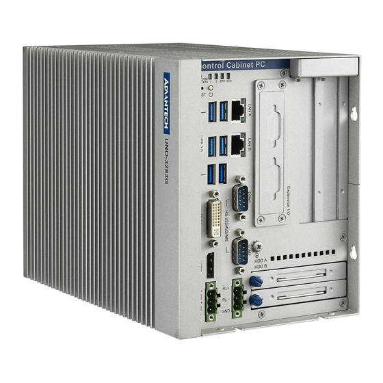
Introduction The following figures show the interfaces of UNO-3200G and detailed information for each peripheral. Figure 2.1 UNO-3283G Front View Figure 2.2 UNO-3285G Front View UNO-3200G Series User Manual... -
Page 19: Serial Interface (Com1/Com2)
Serial Interface (COM1/COM2) UNO-3283G/3285G series offer two standard RS-232/422/485 serial communication interface ports: The IRQ and I/O address of serial ports are listed as below. COM1 (Pin header CN3) COM2 (Pin header CN4) Figure 2.3 Serial Interface (COM1, COM2) 2.2.1 RS-232/422/485 Interface (COM1 &... -
Page 20: To Switch The Internal Sw1/Sw2/Sw3 According To The Placement
2.2.2 To switch the internal SW1/SW2/SW3 according to the placement SW1: COM1 RS232/422/485 mode setting SW3: COM2 RS232/422/485 mode setting Figure 2.4 COM setting SW2: COM1 RS422 Rx termination (pin1-pin2) Figure 2.5 COM1 RS422 Rx termination (pin1-pin2) UNO-3200G Series User Manual... -
Page 21: Lan: Ethernet Connector
SW2: COM2 RS422 Rx termination (pin3-pin4) Figure 2.6 COM2 RS422 Rx termination (pin3-pin4) LAN: Ethernet Connector UNO-3200G series are equipped with two Gigabit LAN controller. The controller chip used is the Intel Ethernet controller with that is fully compliant with 802.1Qav, IEEE1588/802.1AS, 802.3az standards. -
Page 22: Display Connector
Display Connector UNO-3200G series provide a HDMI and DVI-I controller for a high resolution inter- face. It supports up to full HD resolution for up to three independent displays. Note! Independent design of VGA force function VGA force function Description: The default setting for VGA force function is enabled. -
Page 23: Rtc Battery
terminal load. Then the terminal load would lead the EEID signal to force to output. This function is an independent design and doesn’t affect other IO functions or IC cir- cuits. Solution By default, the dummy VGA function is enabled. If you do not use it, please turn SW7 to the ON position to disable the dummy VGA function. -
Page 24: Power Button/Power Management
Power Button/Power Management Press the “PWR” button to power on or power off (ATX type). This product supports the ACPI (Advanced Configuration and Power Interface). As well as power on/off, it supports multiple suspend modes, such as Power on Suspend (S1), Suspend to RAM (S3), and Suspend to Disk (S4). -
Page 25: Pci Express Mini Card Socket
PCI Express Mini Card Socket There are two sockets for full size PCI Express mini cards. The first interface (CN20) is the default defined for mSATA. The second (CN19) interface is mainly targeted to support iDoor technology/ modules for diversified applications such as isolated COM port, Profibus, WLAN GPRS, 3G, and mRAM. -
Page 26: Sata Hdd/Ssd Drive
2.11 SATA HDD/SSD Drive The UNO-3200G series product support two 2.5" SATA HDD/SSD bays with up to 6Gbps speed. The UNO-3200G supports RAID0 and RAID1. The RAID function should be enabled in BIOS setup before you install an operating system into a RAID volume. Users can enable the RAID function in BIOS sub-menu “Advance\SATA Configuration”. -
Page 27: Audio Jack
Create a RAID volume in RAID configuration utility. Figure 2.11 Creating a RAID Volume Follow standard procedures to install OS into a RAID volume. Note! The Maximum height of 2.5" HDD/SSD supported is 9.5 mm, and Maximum Power is 5V / 700mA per SATA port. Hot-swappable function of HDD/SSD is in conflict with operation of RAID0. - Page 28 UNO-3200G Series User Manual...
-
Page 29: Chapter 3 Initial Setup
Chapter Initial Setup This chapter introduces how to initialize UNO-3200G series. Sections include: Chassis Grounding Connecting Power Connecting a Hard Disk BIOS Setup and System Assign- ments... -
Page 30: Connecting Power
Connecting Power Capacity of 12Vdc-36 VDC power source to UNO-3200G series product. The power source can be from either a power adapter or an in-house power source. Figure 3.1 Power Connector Inserting an iDoor Module UNO-3200G series have one iDoor for various expansions. Follow the diagram to install iDoor modules into the system. - Page 31 Insert & lock the mini-PCI card using screws. Replacing the blanking plate with the iDoor plate. Note! For iDoor POE or USB3.0 module, UNO-3200G provides an internal backup power (VO1) on system board. UNO-3200G Series User Manual...
-
Page 32: Installing A Hard Disk
Installing a Hard Disk Follow the steps below to install a HDD/SSD into the system. Release thumb screw and pull out the HDD/SSD bracket. Screw the HDD/SSD to the bracket. Put the bracket back & tighten the thumb screw. Note! Available 130 mm space upon HDD/SSD bracket. -
Page 33: Installing An Interface Card Or Cfast Card
Installing an Interface Card or CFast Card UNO-3200G provides optional backplanes to fulfill extensive requirements in various projects. These backplanes provide PCIe/PCI slots to be compatible with different interface cards. User can install interface cards based on their requirement. UNO- 3200G also provides one internal CFast slot for extending storage. -
Page 34: Mounting Uno-3200G Series
Please use M3 x 5L screws to fasten the wall mount kit on UNO-3283G. Screws for fastening UNO-3283G on wall or desk should not be larger than 4mm. Screw head diameter should be larger than 6mm and less than 7mm. - Page 35 Figure 3.4 Wall Mount (01) Figure 3.5 Wall Mount (02) For safety, install following below suggestion. Also, note that the equipment is intended only for use only in a Restricted Access Area. UNO-3200G Series User Manual...
- Page 36 UNO-3200G Series User Manual...
-
Page 37: System Settings And Pin Assignments
Appendix System Settings and Pin Assignments... -
Page 38: System I/O Address And Interrupt Assignment
System I/O Address and Interrupt Assignment Table A.1: Interrupt Assignments Interrupt# Interrupt source Parity error detected IRQ0 System timer IRQ1 Standard 101/102-Key or Microsoft Natural PS/2 Keyboard IRQ2 Interrupt from controller 2 (cascade) IRQ3 Communications Port (COM2) IRQ4 Communications Port (COM1) IRQ5 Available IRQ6... -
Page 39: Board Connectors And Switches
Board Connectors and Switches There are several connectors and switches on the inside board. The following sec- tions tell you how to configure the hardware setting. Figure A.1 shows the locations of the connectors and switches. Figure A.1 Bottom view of System Board UNO-3200G Series User Manual... -
Page 40: Function Of Connectors & Switches
Function of connectors & switches The connectors and switches on the inside boards are defined as table A.2. Table A.2: Connectors on System board Label Function COM1 setting RS-422/485 receiver termination COM2 setting Power Switch Reset VGA Switch HDMI Audio CN10 LAN &... -
Page 41: Audio (Pin Header)
Audio (Pin header) Table A.3: CN9 Audio Pin Name LOUTR LOUTL LOUT_JD LINR LINL LIN_JD MIC1R MIC1L MIC1_JD UNO-3200G Series User Manual... -
Page 42: Com1/Com2
COM1/COM2 Table A.4: COM POER Pin Definition Connector Function RS232 RS422 RS485 422_TXD- 485_Data- 422_TXD+ 485_Data+ 422_RXD+ 422_RXD- COM3/COM4 Table A.5: RS-232 Serial Port Pin Assignments Pin Name UNO-3200G Series User Manual... -
Page 43: Power Connector (Pwr)
Power Connector (PWR) Table A.6: Power connector pin assignments Relay Connector (PWR) Table A.7: Relay Connector (PWR) RL + Relay Normal Open RL - Relay COM Case Ground UNO-3200G Series User Manual... -
Page 44: Sw4 Power Switch
SW4 Power Switch Table A.8: SW4 Power Switch Part Number 1600000049 Footprint SW-TP33WS83565 Description RESET SW ES-26A-K-T/R-H SMD 4p Pin Name PSIN UNO-3200G Series User Manual... -
Page 45: Cn19/Cn20 Mini Pcie
A.10 CN19/CN20 Mini PCIE Table A.9: CN19/CN20 Mini PCIE Pin Name WAKE# +3.3VSB +1.5V UIM_PWR UIM_DATA REFCLK- UIM_CLK REFCLK+ UIM_RESET UIM_VPP PU3.3_AUX PERST# PERn0 +3.3VSB PERp0 +1.5V SMB_CLK PETn0 SMB_DAT PETp0 USB D- USB D+ +3.3VSB +3.3VSB UNO-3200G Series User Manual... - Page 46 Table A.9: CN19/CN20 Mini PCIE +1.5V +3.3VSB UNO-3200G Series User Manual...
-
Page 47: Cn20 Msata
A.11 CN20 mSATA Table A.10: CN20 mSATA Pin Name WAKE# +3.3VSB +1.5V UIM_PWR UIM_DATA REFCLK- UIM_CLK REFCLK+ UIM_RESET UIM_VPP PU3.3_AUX PERST# SATA_RX+ +3.3VSB SATA_RX- +1.5V SMB_CLK SATA_TX- SMB_DAT SATA_TX+ USB D- USB D+ +3.3VSB +3.3VSB UNO-3200G Series User Manual... - Page 48 Table A.10: CN20 mSATA +1.5V +3.3VSB UNO-3200G Series User Manual...
-
Page 49: Vo1 Reserve For Power Output, The Voltage Is Same As Power Input
A.12 VO1 reserve for power output, the voltage is same as power input Table A.11: VO1 reserve for power output, the voltage is same as power input Pin Name Note! This connector support max 2 A. UNO-3200G Series User Manual... -
Page 50: Cn1 Internal 12V Power For Pci/Pcie
A.13 CN1 Internal 12V power for PCI/PCIe This connector support 12V(3A). Table A.12: CN1 Internal 12V power for PCI/PCIe Name UNO-3200G Series User Manual... - Page 51 UNO-3200G Series User Manual...
- Page 52 No part of this publication may be reproduced in any form or by any means, electronic, photocopying, recording or otherwise, without prior written permis- sion of the publisher. All brand and product names are trademarks or registered trademarks of their respective companies. © Advantech Co., Ltd. 2022...
Need help?
Do you have a question about the UNO-3283G and is the answer not in the manual?
Questions and answers