
Subscribe to Our Youtube Channel
Related Manuals for Fischer Panda PMS 5000 LPE


Summary of Contents for Fischer Panda PMS 5000 LPE
- Page 1 Operation manual Description of the generator and operation manual Panda PMS 5000 LPE Super silent technology 230 V - 50 Hz 120 V - 60 Hz / 4 kW Fischer Panda...
-
Page 2: Current Revison Status
Duplication and change of the manual is permitted only in consultation with the manufacturer! Fischer Panda GmbH, 33104 Paderborn, reserves all rights regarding text and graphics. Details are given to the best of our knowledge. No liability is accepted for correctness. Technical modifications for improving the product without previous notice may be undertaken without notice. -
Page 3: Table Of Contents
Table of contents Current revison status ......................2 Safety first ..........................8 Tools ............................9 Safety Precautions ....................... 11 5 Safety steps to follow if someone is the victim of electrical shock ......13 WHEN AN ADULT STOPS BREATHING................14 The Panda Generator.................... - Page 4 Table of contents C.5.1 Installation of the standard exhaust system ............... 49 C.5.2 Exhaust / water separator ....................50 C.5.3 Installation exhaust/water separator .................. 51 C.6 Fuel System Installation ....................53 C.6.1 General References ......................53 C.6.2 The electrical fuel pump ..................... 54 C.6.3 Connection of the fuel lines at the tank ................
- Page 5 Table of contents Coolant connection block at generator housing ............84 Conservation at longer operation interruption ............85 E.8.1 Measures on preparation of the winter storage ..............85 E.8.2 Initiation at spring ......................86 Generator Failure ......................87 Tools and measuring instruments ................87 Overloading the Generator ....................
- Page 6 Table of contents A.6 Starting preparation / Checks (daily) ................118 A.6.1 Marine version ......................... 118 A.6.2 Vehicle version ........................ 119 A.7 Starting and stopping the generators ................. 119 A.7.1 Starting the generator ...................... 119 A.7.2 Stopping the generator ....................120 A.8 Automatic adapter - option ..................
- Page 7 Fischer Panda GmbH, 33104 Paderborn, reserves all rights regarding text and graphics. Details are given to the best of our knowledge. No liability is accepted for correct- ness. Technical modifications for improving the product without previous notice may be undertaken without notice. Before installation, it must be ensured that the pictures,...
-
Page 8: Safety First
Safety first These symbols are used throughout this manual and on labels on the machine itself to warn of the possibility of per- sonal injury. Read these instructions carefully. It is essential that you read the instructions and safety regulations before you attempt to assemble or use unit. -
Page 9: Tools
Tools This symbols are used throughout this manual to show which tool must be used at maintenance or installation. Spanners X = required size Hook wrench for oil filter Screw driver, for slotted head screws and for recessed head screws Multimeter, multimeter with capacitor measuring Socket wrench set Hexagon wrench keys... - Page 10 2. The installation certificate must be despatched within two weeks of use to Fischer Panda. 3. The official guaranty confirmation will be completed by Fischer Panda after receipt and sent to the customer. 4. A guaranty must be shown to make any claims.
-
Page 11: Safety Precautions
Safety Precautions The electrical installations may only be carried out by trained and qualified personnel! Safety Instructions concerning operating the generator • The generator must not be taken into use with the cover removed. • If the generator is being installed without a sound insulation capsule, then make sure, that all rotating parts (belt- pulley, belts etc) are covered and protected so that there is no danger to life and body! •... - Page 12 Safety Instructions concerning the capacitors Capacitors are required to run the generator. These have two varying functions: A) The working capacitors B) The (Booster) capacitors Both Groups are located in a separate AC-Control box. Capacitors are electrical stores. There could be a residual of high electrical current at the contacts for a period dis- connection from the circuit.
-
Page 13: Safety Steps To Follow If Someone Is The Victim Of Electrical Shock
5 Safety steps to follow if someone is the victim of electrical shock Do not try to pull or grab the individual. Send for help as soon as possible. If possible, turn off the electrical power. If you cannot turn off the electrical power, pull, push, or lift the person to safety using a wooden pole, rope, or some nonconductive material. -
Page 14: When An Adult Stops Breathing
WHEN AN ADULT STOPS BREATHING WARNING DO NOT attempt to perform the rescue breathing techniques provided on this page, unless certified. Performance of these techniques by uncertified personnel could result in further injury or death to the victim. Does the Person Respond? Shout, "Help!"... -
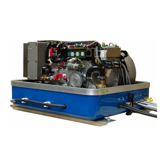
Page 15: The Panda Generator
The Panda Generator B. The Panda Generator B.1 Typeplate at the Generator Fig. B.1-1: Typenschild Fig. B.1-2: Typenschildbeschreibund 21.10.08 Panda PMS 5000LPE_Operationinstruction.R04 - Kapitel B: The Panda Generator Seite 15... -
Page 16: Description Of The Generator
The Panda Generator B.2 Description of the Generator B.2.1 Right Side View 01. Terminal block for remote control panel, fuses and relays 10. Fuel pump cable (2x1,5mm²) 02. Raw water hose 11. Remote control panel cable (12x1mm²) 03. Toothed belt 12. -
Page 17: Left Side View
The Panda Generator B.2.2 Left Side View 01. Ventilation valve generator housing 08. Water pump (inside sound cover base part) 02. Lifting device 09. Connection for external expansion valve 04. Cooling water hose to engine 10. Injection nozzle 05. Generator housing with coil 11. -
Page 18: Front View
The Panda Generator B.2.3 Front View 01. Suction port at air suction housing 11. Failure bypass switch 02. Air suction housing with air filter inlet 12. Oil drain hose 03. Thermo-switch engine 13. Fuel solenoid valve 04. Solenoid switch for starter motor 14. -
Page 19: Back View
The Panda Generator B.2.4 Back View 01. Power terminal box 07. Generator front cover 02. Starter motor 08. Ball bearing flange 03. Cooling water tank 09. Cooling water connection block 04. Cooling water hose, water pump to connection block 10. Exhaust outlet 05. -
Page 20: View From Above
The Panda Generator B.2.5 View from Above 01. Connection external ventilation valve 09. Cooling water filler neck 02. Cooling water tank 10. Air suction housing with air filter 03. Water pump 11. Solenoid switch for starter motor 04. Heat exchanger 12. -
Page 21: Details Of Functional Units
The Panda Generator B.3 Details of functional units B.3.1 Remote control panel - SEE SEPARATE DATASHEET The remote control panel is necessary to control the generator and to evaluate the motor/genera- tor properties. The generators will automatically cutout if it does not run as required. The genera- tor may not be run without the remote control panel. - Page 22 The Panda Generator Heat exchanger Separates the raw water system from the freshwater system. Fig. B.3.2-3: Heat exchanger Ventilation valve A siphon must be installed if the generator sinks below the water line because of the rocking of the boat, even if it is only for a short period of time.
-
Page 23: Components Of Cooling System (Freshwater)
The Panda Generator B.3.3 Components of Cooling System (Freshwater) Cooling water filler neck The cooling water filler necks situated at the water-cooled manifold are only used, when the generator is initially started. Since the generator is normally already filled with cooling water, these compo- nents are only by the user, if repairs are to be carried out. - Page 24 The Panda Generator Heat exchanger Separates the raw water system from the freshwater system. Fig. B.3.3-4: Heat exchanger Water pump The water pump delivers the fresh water to the cooling water connection block. Fig. B.3.3-5: Water pump Cooling water connection block The cooling water is fed to the generator and drained via the cooling water connec- tion block.
- Page 25 The Panda Generator Ventilation valve generator housing The ventilation valve on the generator housing should occasionally be opened for control purposes. Standing machinery should principally carry out ventilating. Fig. B.3.3-7: Ventilation valve generator housing Water pipe engine After the cooling water has flown through the generator housing it is lead to the engine.
-
Page 26: Components Of The Fuel System
The Panda Generator B.3.4 Components of the fuel system External fuel pump The Panda generator is always supplied with an external, electrical (12 V of DC) fuel pump. The fuel pump must be always installed in the proximity of the tank. The electrical connections with the lead plan- ned for it are before-installed at the gene- rator. - Page 27 The Panda Generator Injection nozzle If the engine does not start after the venti- lation, the fuel injection line must be de- aerated individually. Fig. B.3.4-4: Injection nozzle Glow plug The glow plug serve the pre-chamber for the heating with cold start. The heat-treat fixture must be operated, if the tempera- ture of the generator is under 16°C.
-
Page 28: Components Of Combustion Air
The Panda Generator B.3.5 Components of combustion air Air suction openings at the sound cover The sound cover for the marine generator is provided at the front side with drillings, through which the combustion air can inf- lux. It must be consistently paid attention that the generator is installed in such a way that no water can arrive into the proximity of these air openings. - Page 29 The Panda Generator Exhaust elbow On the back of the engine is the water- cooled exhaust elbow. On the top side the pipe union for the internal raw water circuit is to be seen. Fig. B.3.5-4: Exhaust elbow Exhaust outlet Connect the exhaust pipe with the water lock.
-
Page 30: Components Of The Electrical System
The Panda Generator B.3.6 Components of the electrical system Connection starter battery 1. Cable for starter battery (plus) 2. Cable for starter battery (minus) During the connection to the starter bat- tery it must be always ensured that the contact is perfectly guaranteed. Fig. - Page 31 The Panda Generator Actuator for speed regulation The generator voltage is determined by progressive speed control through "VCS" in conjunction with the speed actuator. Speed increases with increasing load. Fig. B.3.6-4: Actuator Generator power terminal box At the top of the generator is the power terminal box.
-
Page 32: Sensors And Switches For Operating Surveillance
The Panda Generator B.3.7 Sensors and switches for operating surveillance Thermo-switch at engine The thermo-switch at the engine serves the monitoring of the generator tempera- ture. All thermo-switches for the genera- tors from Panda 6.000 upward are two- pole and laidout as "openers". Fig. -
Page 33: Components Of The Oil Circuit
The Panda Generator Oil pressure switch In order to be able to monitore the lubrica- ting oil system, an oil pressure switch is built into the system. Fig. B.3.7-4: Oil pressure switch Failure bypass switch The failure bypass switch offers the possi- bility of starting the generator if the electri- cal control switched off due to an error in the cooling system by overheating. - Page 34 The Panda Generator Oil dipstick At the dipstick the permissible level is indi- cated by the markings "maximum" and "minimum". The engine oil should be never filled up beyond the maximum con- ditions. Fig. B.3.8-2: Oil dipstick Oil strainer The oil strainer should be cleaned every 500 operating hours.
-
Page 35: External Components
The Panda Generator B.3.9 External components AC-Control box For the operation of the generator a AC- Control box is necessary. This AC-Control box contains electronics for the VCS con- trol as well as different monitoring ele- ments and the capacitors necessary for the excitation of the generator. - Page 36 The Panda Generator Voltage control VCS The figure shows the control printed board for the VCS voltage regulation. Over this control printed board the control signals are given for the actuator for speed regu- lation. On the VCS board are also adjust- ment possibilities control...
-
Page 37: Operation Manual
Sample Picture Tips regarding Starter Battery Fischer Panda recommends normal starter battery use. If an genset is required for extreme win- ter conditions, then the starter battery capacity should be doubled. It is recommended that the starter battery be regularly charged by a suitable battery-charging device (i.e., at least every 2 Months). -
Page 38: Daily Routine Checks Before Starting
The Panda Generator B.4.2 Daily routine checks before starting 1. Oil Level Control (ideal level: MAX). AtTTENTION! OIL PRESSURE CONTROL! True, the diesel motor automatically switches off when there is a lack of oil, but it is very damaging for the motor, if the oil level drops to the lowest limit. -
Page 39: Starting Generator
The Panda Generator B.4.3 Starting Generator 1. If necessary, open the fuel valve. 2. If necessary, close the main battery switch. 3. Check if all the load have been switched off. The load is switched off, before the generator is switched off. The generator is not to be started with load connec- ted. -
Page 40: Stopping The Generator
The Panda Generator B.4.4 Stopping the Generator 1. Switch off load. 2. If the load is higher than 70% of the nominal load, the generator temperatures should be stabi- lised by switching off the load for at least 5 minutes. At higher ambient temperatures (more than 25°C) the generator should always run for at least 5 minutes without load, before it is switched off, regardless of the load. -
Page 41: Installation Instruction
Installation Instruction C. Installation Instruction C.1 Placement C.1.1 Placement and Basemount Since Panda generators have extremely compact dimensions they can be installed in tight locati- ons, attempts are sometimes made to install them in almost inaccessible places. Please consider that even almost maintenance-free machinery must still remain accessible at least at the front (drive belt, water pump) and the service-side (actuator, dipstick). -
Page 42: Generator Connections - Scheme
Installation Instruction C.2 Generator Connections - Scheme The generator comes supplied with all supply lines (i.e. electric cables, fuel lines etc.) already connected to the motor and generator. The supply lines are fed through the capsule's front base panel and are shielded at the capsule inlets with water-proof grommets. All electrical connections, cable types and sizes must comply to the appropriate regulati- ons. -
Page 43: Cooling System Installation - Raw Water
Installation Instruction C.3 Cooling System Installation - raw water C.3.1 General References The genset should have its own sea water (coolant water) inlet and should not be connected to any other engine systems. Ensure that the following installation instructions are complied with: Avoid galvanic corrosion For the avoidance of galvanic corrosion the chapter "Service instruction for marine aggregates (corrosion protection)“... -
Page 44: Installation Above Waterline
A repair is then very expensive. Replacement impeller and also a spare pump should always be on board. The old pump can be sent back to Fischer Panda, where it is then economically overhauled completely. 1. Raw water filter 2. Water cock 3. -
Page 45: Installation Below Waterline
Installation Instruction C.3.5 Installation below waterline If the generator can not be attached at least 600mm over the waterline, a vent valve must be installed into the raw water line. With location beside the "midship line" a possible hee- ling must be considered! The water hose for the external vent valve at the back of the sound cover splits on the pres- sure side of the pump and at both ends in each case exten- ded with a connecting nipple by a hose end. -
Page 46: The Freshwater - Coolant Circuit
Installation Instruction C.4 The Freshwater - Coolant Circuit Fig. C.4-1: Freshwater Circiut - Scheme C.4.1 De-aerating at the first filling of the internal cooling water circuit 1. For the preparation of filling the following steps are to be undertaken: a. Open the cooling water cap on the housing of the water-cooled exhaust elbow union, Seite 46... - Page 47 Installation Instruction b. Ventilation valve on the generator hou- sing, 2. Filling the cooling water circle a. Fill in the prepared mixture (cooling water with anti-freeze protection accord- ing to the intended mixture) at the filler neck at the housing of the water-cooled exhaust elbow union slowly so long, until cooling water leaks at the de-aerating screw of the thermostat housing.
-
Page 48: Pressure Test For Control Of Cooling Water Circuit
Installation Instruction 3. First de-aerating The cooling water circuit of the generator must be de-aerated now by multiple repeating of the de-aerating procedure. During the entire procedure the external cooling water expansion tank remains opened (i.e. the cap must be removed). After the first stopping of the the generator wait about one minute until the air in the cooling water can be drop off and raise to the highest point (ventilation point). -
Page 49: Watercooled Exhaust System
Installation Instruction C.5 Watercooled Exhaust System By injecting the outlet raw water into the exhaust manifold, the exhaust gases are cooled and the noise emissions from the exhaust system are reduced. C.5.1 Installation of the standard exhaust system The generator exhaust system must remain completely independent and separate from the exhaust system of any other unit(s) on board. -
Page 50: Exhaust / Water Separator
Additionally there is component at Fischer Panda, which exercise both functions of a "exhaust goose neck", and the water separa- tion. With this "exhaust/water separator" the cooling water is derived over a separate pipe. The- reby the exhaust noises at the exterior of the yacht are strongly decreased. -
Page 51: Installation Exhaust/Water Separator
Installation Instruction C.5.3 Installation exhaust/water separator If the exhaust/water separator was sufficiently highly installed, a goose neck is no longer neces- sary. The exhaust/water separator fulfills the same function. If the "Supersilent" exhaust system were installed correctly, the generator will not disturb your boat neighbour. The exhaust noise should be nearly inaudible. - Page 52 Installation Instruction Example of an unfavorable installation: - water lock not deeply enough under the hights level of the generator - distance water lock to exhaust/water separator too largely Seite 52 Panda PMS 5000LPE_Operationinstruction.R04 - Kapitel C: Installation Instruction 21.10.08...
-
Page 53: Fuel System Installation
Installation Instruction C.6 Fuel System Installation C.6.1 General References Inside the generator capsule itself, there is the fuel filter installed (Exception Panda 4500). Addi- tional fuel filters (with water seperator) must be mounted outside the capsule in easily accessible places in the fuel lines between the tank intake fuel pump and the diesel motor's fuel pump. Generally forward and return fuel flow pipes must be mounted to the diesel tanks. -
Page 54: The Electrical Fuel Pump
Installation Instruction C.6.2 The electrical fuel pump Electrical fuel pump With the Panda generator is usually supp- lied an external, electrical fuel pump (12V DC). The fuel pump must be installed close at the fuel tank. The electrical con- nections are preloaded at the generator with the lead planned. -
Page 55: Position Of The Pre-Filter With Water Separator
Installation Instruction C.6.4 Position of the pre-filter with water separator Additionally to the standard fine filter a pre- filter with water separator must be installed outside of the sound cover in the fuel sys- tem line. (is not included in delivery.) C.6.5 Bleeding air from the fuel system Normally, the fuel system is designed to bleed out air itself i.e. -
Page 56: Generator 12V Dc System-Installation
Installation Instruction C.7 Generator 12V DC System-Installation The Panda has its own dynamo to charge a 12V starter battery. It is recommended to install an additional starter battery for the generator. The generator is then independent from the remaining battery set. This enables you to start the genset at any time with its own starter battery even if the other batteries are discharged. - Page 57 Installation Instruction The Panda generators 8000 to 30 are equipped with various DC-relays, which can be found under the terminal strip. The various relays have the following tasks (also see the DC circuit diagram) 1. Starter motor relay 2. Pre-glow relay (glow plugs) 3.
-
Page 58: Generator Ac System-Installation
Installation Instruction C.8 Generator AC System-Installation ATTENTION! Before the electrical system is installed, READ the “Safety first” on page 6 of this manual FIRST! Be sure that all electrical installations (including all safety systems) comply with all required regulations of the regional authorities. This includes lightnening conductor, personal protection switch etc. -
Page 59: Installation Ac-Box / Distribution Panel Separate Connected
Installation Instruction C.8.2 Installation AC-Box / distribution panel separate connected 1. Generator 4. Distribution panel 2. Battery 5. Remote control panel 3. AC-Control Box 6. Fuel pump A power source selector switch must be installed between the generator (or if applicable, AC-Control box) and the ship´s electrical supply system. - Page 60 Installation Instruction The cam-type switch must have 2 poles, so that "MP" and "phase" can be switched off. If a 3-phase current system is also installed with the option of supplying from either the generator or shore power, an additional switch must be installed to keep these systems separate. An alternative to a manual rotating switch is an automatic power relay.
-
Page 61: Ac-Control Box With Vcs And Asb
Installation Instruction C.8.3 AC-Control box with VCS and ASB In the AC-Control box the needed capacitors for the excitation of the generator are placed as well as the electronic control for voltage/speed regulation VCS and the starting current reinforcement ASB. The AC-Control box must be connected with the conductions (high voltage and low-voltage) to the generator. -
Page 62: Vcs-Voltage Controll
Installation Instruction C.8.4 VCS-voltage controll All Panda generators from Panda 8000 upwards are fitted with the electronic voltage control "VCS" as standard. The VCS controls the generator voltage and motor speed. A servo motor on the injection pump can increase the engine speed by up to 8%. If the generator is run without load, the voltage should be 231V with a frequency of approx 48.5 to 49Hz. -
Page 63: Jump Start At Hight Starting Current (Booster)
Installation Instruction C.8.5 Jump start at hight starting current (Booster) Additionally, the automatic start booster is located on the circuit control board. The starting cur- rent is increased by connecting a second group of capacitors (C2), if the voltage drops below a pre-set voltage. -
Page 64: Instructions On Preventation Of Galvanic Corrosion
Strict separation of the generator from 12V ship mains, that means earth free installation of the 12V system (generator installation and general ship mains). Please take more details from the information pack "Bimetalic Corrosion (Electrolysis)", which You can order from Fischer Panda gratis. Seite 64 Panda PMS 5000LPE_Operationinstruction.R04 - Kapitel C: Installation Instruction... -
Page 65: Mode Of Operation Of The Generator
Mode of Operation of the Generator D. Mode of Operation of the Generator D.1 Mode of Operation of Operating Surveillance Internal monitoring switches The generator is equipped about failure switches, which are indicated on the remote control panel, and also about failure switch, which switch-off the generator automatically without indica- ting a failure in the remote control panel: The remote control panel supervised the following values. - Page 66 Mode of Operation of the Generator Thermo-switch at exhaust connection If the impeller pump drop out and delive- res no more raw water, the exhaust con- nection becomes extremely hot. Fig. D.2: Thermo-switch at exhaust connection Thermo-switch in the generator coil 1.
-
Page 67: Regulation Of The Generator Voltage By The Vcs
Mode of Operation of the Generator D.1.1 Regulation of the generator voltage by the VCS The output voltage of the generator is permanently measured by the VCS (approx. 20 times per second!). As soon as by a consumer the voltage is affected, the speed regulation provides to adapt to the changed power demand by appropriate change of the engine speed. -
Page 68: Use The Failure Bypass Switch For The Fuel Delivery
If such engines are to be operated, contact the techni- cian of Fischer Panda, in order to find suitable measures, which work against the high starting current and/or layout the generator for the higher starting current. -
Page 69: Operation Of The Generator With Automatic Start
Mode of Operation of the Generator D.3 Operation of the generator with automatic start If the generator set were set up far away from the location of the remote control panel that the user cannot hear surely, whether the generator starts, a automatic starting option (accessories) should be installed. -
Page 70: Control Of The Vent Valve
Mode of Operation of the Generator 1) Hull inlet 7) Fresh water pump 2) Water cock 8) Exhaust manifold, water-cooled 3) Reducer 9) External vent valve 4) Raw water filter 10) Diode block, water-cooled 5) Raw water pump 11) Cooling water tank 6) Heat exchanger D.4.1 Control of the vent valve If the valve is blocked, the cooling water pipe cannot be ventilated after the stop of the generator,... - Page 71 Mode of Operation of the Generator 1. Raw water filter 2. Water cock 3. Hull inlet Make certain that the sea water filter lies above the water level, otherwise with cleaning water can penetrate by the hull inlet. An external pre-pump can relieve the impeller.
- Page 72 Mode of Operation of the Generator Blank Seite 72 Panda PMS 5000LPE_Operationinstruction.R04 - Kapitel D: Mode of Operation of the Generator 21.10.08...
-
Page 73: Maintenance Instructions
Maintenance Instructions E. Maintenance Instructions E.1 General maintenance instructions E.1.1 Checks before starting • Oil level • Cooling system leaks • Visual check for any changes, leaks oil drain system, v-belt, cable connections, hose clips, air filter, fuel lines Every 100h •... -
Page 74: Execution Of An Oil Change
Maintenance Instructions E.2 Execution of an oil change Oil drain hose For the oil change an oil drain hose is lead through the sound cover. Oil drain screw The oil can be discharged by opening the oil drain screw. For countering use a second wrench. - Page 75 Maintenance Instructions Oil strainer The oil strainer must be cleaned every 500 opeatiing hours. Open the oil filler neck After opening the cap of the oil filler neck the new oil is refilled. Please wait instant, before measure the oil level, the oil must set off in the sump.
-
Page 76: Checking The Water Separator In The Fuel Supply
Maintenance Instructions E.3 Checking the water separator in the fuel supply The pre-filter with water separator has a cock at its lower surface, with this cock the downward sunk water can be discharged. This is simply possible, water is heavier due to its density than the Diesel. -
Page 77: Exchange The Air Filter
Maintenance Instructions 3. After the fuel pump has been running 3 to 4 minutes because the failure bypass switch has been pushed down the bleeding screw of the solenoid valve has to be unscrewed. When ope- ning the screw one has to carry on pushing the switch. -
Page 78: Aerating Of The Coolant Circuit / Freshwater
Maintenance Instructions Change the air filter mat and close the cover again. E.4 De-aerating of the coolant circuit / freshwater Special notes for the ventilation of the cooling system If the cooling water is drained or if other air should have arrived into the cooling system, it is necessary to de-aerate the cooling system. -
Page 79: Exchange Of The V-Belt For The Internal Cooling Water Pump
Maintenance Instructions Fill in cooling water into the cooling water filler neck. If it is to be recognized that the cooling water level does not fall anymore (with cold cooling water the cooling water levelmust cover the sheet metal in the exhaust elbow), close the filler-cap and the ventilation valves and start the gener- ator. - Page 80 Maintenance Instructions Down-pull the toothed belt and put a new Type of toothed belt: Gate power Grip GT MR (HTD-410-6-692-M5). Screw on the raw water pump again. Fasten the fixing bolts to the raw water pump again. Seite 80 Panda PMS 5000LPE_Operationinstruction.R04 - Kapitel E: Maintenance Instructions 21.10.08...
-
Page 81: The Raw Water Circuit
Maintenance Instructions E.5 The raw water circuit E.5.1 Clean raw water filter The raw water filter should be released regularly from arrears. In each case the water cock must be closed before. It is mostly sufficient to beat the filter punnet. If water should seep through the cover of the raw water filter, this may be sealed in no case with adhesive or sealant. -
Page 82: Exchange Of The Impeller
Maintenance Instructions E.6.1 Exchange of the impeller Close the raw water stop cock. Raw water pump on the front side of the genset. Remove the cover of the raw water pump by loosen the wing screws from the hou- sing. Seite 82 Panda PMS 5000LPE_Operationinstruction.R04 - Kapitel E: Maintenance Instructions 21.10.08... - Page 83 Maintenance Instructions Pull to the impeller with a multigrip pliers of the wave. Mark the impeller, to make sure that these is used in the correct position at re-instal- lation. Check to the impeller for damage and replace it if necessary. Before the reinsertion into the housing the impeller should have been lubricated with glycerin or with a non-mineral oil based...
-
Page 84: Coolant Connection Block At Generator Housing
Maintenance Instructions E.7 Coolant connection block at generator housing Monitoring of the coolant connection block as sacrificial anode At all raw watercooled aggregates the coolant connection block at the side of the generator hou- sing must be well controlled. This coolant connection block is manufactured from a special alumi- num alloy and serves also as sacrificial anode. -
Page 85: Conservation At Longer Operation Interruption
Maintenance Instructions E.8 Conservation at longer operation interruption E.8.1 Measures on preparation of the winter storage 1. Rinse raw water circuit with an anti-freeze solution, even if this contains a corrosion protection means. The raw water inlet must be removed at the water cock. Over a hose connector the anti-freeze protection mixture is to be sucked in from a container. -
Page 86: Initiation At Spring
Maintenance Instructions E.8.1 Measures on preparation of the winter storage (Forts.) 16.Check cooling water connection block at the generator housing on traces of corrosion and if necessary renew. (only such traces are to be considered, which refer to clear "blossoming" of the material. -
Page 87: Generator Failure
Generator Failure F. Generator Failure Tools and measuring instruments In order to be able to manage disturbances while driving, following tools and measuring instruments should belong to the equipment on board: • Multimeter for voltage (AC), frequency and resistance • Measuring instrument for inductance •... -
Page 88: Monitoring The Generator Voltage
Generator Failure Overloading the Generator with Electric Motors With the operation of electric motors it must be considered that these take up a multiple of their rated output as starting current (six to tenfold). If the power of the generator for the engine is not sufficient, the voltage in the generator breaks down after switching on the engine. -
Page 89: Adjusting Instructions For The Spindle Of The Actuator
Generator Failure Adjusting Instructions for the Spindle of the actuator There is an independent regulation devices for the speed range of the generator. Limited upward and downward: With the regulation nuts at the spindle of the actuator left and right of the spindle nut. After all work at the components of the speed regulation is done the adjustment of the limitation must be checked. -
Page 90: Lubrication Of The Spiral Thread Spindle
Generator Failure 1. Adjusting nut for upper speed limitation 2. Adjusting nut for lower speed limitation If the adjustment is finished the plug of the actuator must be re-connect for operation. Re-connect the connections if the electrical supply lines in the AC-control box were also be dis- connected. -
Page 91: Effects Of A Overload To The Actuator
Generator Failure F.3.3 Effects of a overload to the actuator If the generator is overloaded the voltage falls on account of a not adequate motor power under the nominal value. The actuator stays at the upper keystroke and tries to rev up the diesel engine. An internal regulation limits the current to the actuator, nevertheless a longer overload can damage the winding of the actuator. - Page 92 Generator Failure Steps to check the voltage control by a disturbance: 1. Switch off all electrical consumers. 2. Disconnect the plug of the actuator. 3. Turn the actuator manually to check if the adjusting nut is jamed to the limit stop points. 4.
-
Page 93: Low Generator-Output Voltage
Generator Failure Low Generator-Output Voltage If the produced alternating voltage is too low, switch the consumers off, in order to relieve the generator. Mostly the problem already solved. If the output voltage is still too low, even if all con- sumers are switched off, the generator runs without load, you can assume one or more conden- sers are defective. -
Page 94: Checking The Generator Voltage
Generator Failure Should a steady sound or no sound have to be heard, the capacitor is defective and must be replaced. In order to go surely that the capacitor has still its full capacity, use a capacity measuring instrument. The capacitors, which not achieve the imprinted capacity value at this measurement, should be exchanged as fast as possible. -
Page 95: Checking The Coil(S) To Short-Circuit
Generator Failure F.4.5 Checking the coil(s) to short-circuit In order to check the coils for short-circuit, first all lines, which lead to the electrical system, must be interrupted. This happens on the power terminal box of the generator or, if available, in the electrical system junction box. -
Page 96: Generator Provides No Voltage
Generator Failure Generator provides no Voltage F.5.1 Rotor Magnetism Loss and "Re-magnetizing" .ATTENTION! “Safety first” on Page 6 With asynchronous generators it can be the fact that the generator can not build up indepen- dently voltage after longer service lives, or, if it were switched off under full load. The cause lies in the fact that the rotor lost its remainder magnetism. -
Page 97: Failure Bypass Switch
Generator Failure Fuel solenoid valve F.6.2 Failure Bypass Switch The start-failure bypass switch enables an immediate restart facility of the generator, should it cut out, even if this was caused by over-heating. There is normally a requirement to wait until the motor has cooled down to the correct temperature. -
Page 98: Troubleshooting Table
Generator Failure This period can be reduced by pushing the button on the front of the generator. The generator can be started by means of the remote control as long as the button is depressed. The switch/but- ton bypasses any faults allowing the generator to run. Before depressing the button, a manual check of the oil dip stick must be carried out to determine whether the generator has sufficient oil, as it is possible that the oil pressure switch causes the generator to cut out. -
Page 99: G Tables
Tables G. Tables G.1 Troubleshooting GENERATOR OUTPUT VOLTAGE TOO LOW For 50Hz versions: less than 200V For 60Hz versions: less than 100V Cause Solution Generator is overloaded. Reduce the electrical load. (Switch off consumers) Motor is not reaching the rated rpm. Refer to "motor faults"... - Page 100 Tables DIESEL MOTOR FAILS TO START Cause Solution Starter battery switched "OFF". Check position of battery switch and switch "ON" (if installed). Starter battery voltage insufficient (battery too weak). Inspect battery terminals and cables for a good electri- cal connection (Inspect against corrosion, tattered wires, etc.).
- Page 101 Tables MOTOR RUNS IRREGULARLY Cause Solution Faulty centrifugal injector governor. Have the centrifugal governor inspected by a Kubota- Service technician. Too much air in fuel lines. Bleed air from fuel system. MOTOR SPEED DROPS Cause Solution Lack of fuel Check fuel supply system: - fuel filter, renew if necessary - check fuel pump - check fuel lines (bleed if necessary)
- Page 102 Tables MOTOR STOPS BY ITSELF Cause Solution Lack of fuel. Check fuel supply system. Excess heat in cooling system (thermo switch tripped)- Check cooling water system flow: water pump, inlet lack of cooling water. Is indicated on the remote control water filter, extra heat exchanger coolant flow.
-
Page 103: Technical Data
Tabelle 1: Diameter of conduits Ø Cooling water conduit Ø Fuel conduit Ø Exhaust con- duit Freshwater Raw water Supply Return Generator type [mm] [mm] [mm] [mm] [mm] Panda PMS 5000 LPE 21.10.08 Panda PMS 5000LPE_Operationinstruction.R04 - Kapitel G: Tables Seite 103... -
Page 104: Types Of Coil
Tables G.3 Types of coil HP1 - 230V / 50 Hz HP1 - 120V / 60 Hz HP3 - 400V / 50 Hz Seite 104 Panda PMS 5000LPE_Operationinstruction.R04 - Kapitel G: Tables 21.10.08... - Page 105 Tables HP3 - 120V / 60 Hz DVS - 400V / 50 Hz DVS - 120V 240V / 60 Hz 21.10.08 Panda PMS 5000LPE_Operationinstruction.R04 - Kapitel G: Tables Seite 105...
-
Page 106: Inspection Checklist For Services
Tables G.4 Inspection checklist for services Inspection-Category Inspection work 100 h check change Installation check 500 h measure sealing clean check isolation daily 1000 h 35 - 50 h 5000 h Inspection-Category Inspection work coolant water hoses raw water pump (impeller) water separator / fuel pre-filter engine oil oil strainer... -
Page 107: Engine Oil
Tables G.5 Engine oil Engine oil classification Operating range: The operating range of an engine oil is determined by SAE class. "SAE" is for the union of American engineers (Society of Automotives Engineers). The SAE class of an engine oil only informs over the viscosity of the oil (lar- ger number = more viscous, lower number = more highly liquidly) e.g. -
Page 108: Coolant Specifications
Use a mixture of water and antifreeze. The antifreeze needs to be suitable for aluminium. The antifreeze concen- tration must be regularly checked in the interests of safety. Fischer Panda recommend to use the product: GLYSANTIN PROTECT PLUS/G 48 Engine coolant automotive industry Product description Product name GLYSANTIN ®... -
Page 109: Measurements
Tables G.7 Measurements 21.10.08 Panda PMS 5000LPE_Operationinstruction.R04 - Kapitel G: Tables Seite 109... - Page 110 Tables Seite 110 Panda PMS 5000LPE_Operationinstruction.R04 - Kapitel G: Tables 21.10.08...
-
Page 111: Generator Control Panel P6+ Manual
Generator Control Panel P6+ Manual 12V version - 21.02.02.009H 24V special version - 21.02.02.012H Option automatic adapter - 21.02.02.016H Option master-slave adapter - 21.02.02.015H Fischer Panda GmbH... -
Page 112: Current Revision Status
Current revision status Document Actual: Panel Generator Control P6+ RE0703_Kunde_eng.R02_21.10.08 Replace: Panel Generator Control P6+ RE0703_Kunde_eng.R01_28.11.07 Revision Page Upgrade the whole manual ATTENTION!: Please read the safety instructions in your generator manual! -
Page 113: General Operation
General operation A. General operation A.1 Panel Generator Control Fischer Panda Art. No. 21.02.02.009H 01. LED for coolant temperature red 08. LED for pre-glow „heat“ orange 02. LED for waterleak red/yellow (sensor optional) 09. LED for Generator „start“ green 03. LED for AC-voltage fault red/yellow 10. -
Page 114: Rear View 12V-Version
General operation A.2 Rear view 12V-version Fischer Panda Art. No. 21.02.02.009H 01. Control board 02. Terminal block (master-slave adapter: left row; automatic adapter: right row) 03. Terminals 1-12 (see section A.3.1, “Terminal connections,” on page 104) 04. Fuse 630mA slow-blow Fig. -
Page 115: Rear View 24V-Version
General operation A.3 Rear view 24V-version Fischer Panda Art. No. 21.02.02.012H 01. Control board 02. Terminal block (master-slave adapter: left row; automatic adapter: right row) 03. Fuse 630mA slow-blow 04. Terminals 1-12 (see section A.3.1, “Terminal connections,” on page 104) 05. -
Page 116: Terminal Connections
General operation A.3.1 Terminal connections Standard for NC temperature switch configured i.e. in case of failure „open“. Clamp Clamp IN / Description name Vbat Current supply + 12V (or optional 24V, must be adjusted by jumper) Current supply - Error “coolant temperature”. Input for thermo-switch to GND. The input is adjustable for NC/NO ≥... -
Page 117: Function Of The Jumpers
General operation Notes: 1. Power rating of the output: max. 0,5A in continuous operation and briefly 1,0A. 2. The supply of all output currents may not exceed (less 0,2A power consumption) the rated current of the safety device of the control panel. 3. -
Page 118: Starting Preparation / Checks (Daily)
General operation The solder jumpers are marked on the printed circuit board (with jumper no. and at three-part solder jumper with soldering surface no.) (1): Equivalent resistance for load control lamp e.g. for use with three-phase alternator also integrated automatic controller of Bosch. - Page 119 General operation DC-Control-Signal (-) = OK dynamo 12V at Kubota Z 482 / D 722 engines J208 DC-Control-Signal (+) = OK three-phase DC-alternator DC-Control-Signal (-) = OK dynamo 12V at Kubota Z 482 / D 722 engines J209 DC-Control-Signal (+) = OK three-phase DC-alternator ≥...
- Page 120 General operation Input Water leak has red LED and switches off J206 Input Water leak has yellow LED and does not switch off Input AC-Fault has red LED and switches off J207 Input AC-Fault has yellow LED and does not switch off DC-Control-Signal (-) = OK dynamo 12V at Kubota Z 482 / D 722 engines J208 DC-Control-Signal (+) = OK three-phase DC-alternator...
- Page 121 General operation AC-Fault-input / Fuel level, for contact, which opens in case of error (2) J204 AC-Fault-input / Fuel level, for contact, which closes in case of error (2) T-Winding-input, for contact, which opens in case of error (2) J205 T-Winding-input, for contact, which closes in case of error (2) Input Water leak has red LED and switches off J206...
- Page 122 General operation Water leak-input / Replace air filter, for contact, which opens in case of error (2) J202 Water leak-input / Replace air filter, for contact, which closes in case of error (2) Oil-Press-input, for contact, which opens in case of error (2) J203 Oil-Press-input, for contact, which closes in case of error (2) AC-Fault-input / Fuel level, for contact, which opens in case of error (2)
-
Page 123: Marine Version
General operation A.4 Starting preparation / Checks (daily) A.4.1 Marine version 1. Oil level control (ideal level: 2/3 MAX). The level should be about 2/3 of the maximum level of a cold engine. Further, if installed, the oil level of the oil-cooled bearing must be controlled before each start - see sediment bowl at generator front cover!. -
Page 124: Vehicle Version
General operation A.4.2 Vehicle version 1. Oil level control (ideal level: 2/3 MAX). The level should be about 2/3 of the maximum level of a cold engine. Further, if installed, the oil level of the oil-cooled bearing must be controlled before each start - see sediment bowl at generator front cover!. -
Page 125: Stopping The Generator
General operation A.5.1 Starting the generator 3. Press button „start“ (start engine). LED for "start“ = green. The electric starter may only be used for a maximum of 20 seconds. Thereafter, a pause of at least, 60 seconds is required. If the genset does not immediately start, then the fuel intake should be checked to ensure it is flowing freely. -
Page 126: Automatic Adapter - Option
General operation A.6 Automatic adapter - option Fischer Panda Art. No. 21.02.02.016H 01. Main terminals 02. Automatic adapter 21.02.02.016H 03. 8-pole DIP-switch Fig. A.6-1: Panel 21.02.02.009H with Automatic adapter 21.02.02.016H Function: The automatic adapter RE0704 extends the generator control panel P6+ with an automatic input. A potential-free contact can be attached to this input. - Page 127 General operation The mechanism entrance: With (-) characterized connection is connected to GND. With (+) characterized connection is the input. The input is connected through a resistance to 12V (with 24V-operated internally generated). If the two connec- tions are short circuited over a potential-free contact, then the input current flows. To be considered for an electronic contact the low input current and the polarity is to be selected.
-
Page 128: Terminal Connections
General operation A.6.1 Terminal connections Connection for the automatic adapter X2 (row with odd pin numbers // I/O viwe from operating panel) Pin-no. Pin-name I / O Description Current supply + (operation voltage behind fuse) Current supply - (ground) VBFS Current supply + switched (voltage Pin 1, with panel switched on) Current supply + switched, at 12V-operation over closed soldered jumper J101 connected with VBFS (at optional 24V-operation: VBFS over internal voltage regulator at 12,9V regulated) -
Page 129: Master-Slave Adapter - Option
General operation A.7 Master-Slave adapter - option Fischer Panda Art. No. 21.02.02.015H 12V-version 01. Main terminals 02. Master-slave adapter 21.02.02.015H Fig. A.7-1: Panel 21.02.02.009H with master-slave adapter 21.02.02.015H Fischer Panda Art. No. 21.02.02.01H 24V-version 01. Main terminals 02. Master-slave adapter 21.02.02.015H Fig. -
Page 130: Terminal Connections
General operation With the Master-Slave-Adapter RE0706 two Generator Control Panels P6+ RE0703 can be connected to a Master-Slave-Combination. In addition on each Generator Control Panel P6+ an Master-Slave-Adapter RE0706 is installed. The Generator Control Panel P6+ is interconnected by the 14pole connecting terminals on the Master-Slave-Adapters 1:1. -
Page 131: Configuration And Adjustment
General operation LED-T-Win- Output for LED T-Winding on the Slave panel, is switched to GND, if the LED is illuminated ding Output for LED DC-Control-display on the Slave panel. The DC control signal is ground through DC-Control 1:1. Output for LED AC-Control-display on the Slave panel. The AC control signal is ground through AC-Control 1:1. - Page 132 General operation Jumper Status Conf. Description closed during operation of the start button heat is along-operated open Function deactivated Dynamo excitation resistor 68R is switched on with Fuel-Pump (1) Dynamo excitation resistor 68R is switched on with Panel-ON (1) open Dynamo excitation resistor is deactivated closed 12V - operation...
- Page 133 General operation Configuration and setting sheet KE06 Standard jumpering for use as Slave-Panel in connection with two Maste-Slave-Adapters RE0706 and a Genera- tor Control Panel P6+ RE0703 as Master-Panel. Panel for 24V-operation. (over attitude of solder jumper J101 alternatively 12V-operation is possible) The safety device is installed with the value 0,63AT.
- Page 134 General operation The solder jumpers are marked on the printed circuit board (with jumper no. and at three-part solder jumper with soldering surface no.) X = Jumper must be so set XM = Jumper, function must be so set on the master panel is selected M = Jumper must be set exactly the same, as on the master panel, (1): Equivalent resistance for load control lamp e.g.
-
Page 135: Measurements
Measurements B. Measurements B.1 Hole pattern Fig. B.1-1: Hole pattern 21.10.08 Panel Generator Control P6+ RE0703_Kunde_eng .R02 - Chapter B: Measurements Page 123... - Page 136 Measurements Intentionally Blank Page 124 Panel Generator Control P6+ RE0703_Kunde_eng.R02 - Chapter B: Measurements 21.10.08...
Need help?
Do you have a question about the PMS 5000 LPE and is the answer not in the manual?
Questions and answers