Sign In
Upload
Manuals
Brands
Fischer Panda Manuals
Portable Generator
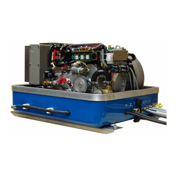
PMS 5000 LPE
Fischer Panda PMS 5000 LPE Manuals
Manuals and User Guides for Fischer Panda PMS 5000 LPE. We have
1
Fischer Panda PMS 5000 LPE manual available for free PDF download: Operation Manual
Fischer Panda PMS 5000 LPE Operation Manual (136 pages)
Brand:
Fischer Panda
| Category:
Portable Generator
| Size: 6 MB
Table of Contents
Current Revison Status
2
Table of Contents
3
Safety First
8
Tools
9
Safety Precautions
11
Safety Steps to Follow if Someone Is the Victim of Electrical Shock
13
When an Adult Stops Breathing
14
The Panda Generator
15
Typeplate at the Generator
15
Description of the Generator
16
Right Side View
16
Left Side View
17
Front View
18
Back View
19
View from above
20
Details of Functional Units
21
Remote Control Panel - SEE SEPARATE DATASHEET
21
Components of Cooling System (Raw Water)
21
Components of Cooling System (Freshwater)
23
Components of the Fuel System
26
Components of Combustion Air
28
Components of the Electrical System
30
Sensors and Switches for Operating Surveillance
32
Components of the Oil Circuit
33
External Components
35
Operation Manual
37
Preliminary Remark
37
Daily Routine Checks before Starting
38
Starting Generator
39
Stopping the Generator
40
Starting the Generator by a „Failure Bypass Switch
40
Installation Instruction
41
Placement
41
Placement and Basemount
41
Notoice for Optimal Sound Insulation
41
Generator Connections - Scheme
42
Cooling System Installation - Raw Water
43
General References
43
Installation of the Thru-Vessel Fitting in Yachts
43
Quality of the Raw Water Sucking in Line
43
Installation above Waterline
44
Installation below Waterline
45
The Freshwater - Coolant Circuit
46
Aerating at the First Filling of the Internal Cooling Water Circuit
46
Pressure Test for Control of Cooling Water Circuit
48
Watercooled Exhaust System
49
Installation of the Standard Exhaust System
49
Exhaust / Water Separator
50
Installation Exhaust/Water Separator
51
Fuel System Installation
53
General References
53
The Electrical Fuel Pump
54
Connection of the Fuel Lines at the Tank
54
Position of the Pre-Filter with Water Separator
55
Bleeding Air from the Fuel System
55
Generator 12V DC System-Installation
56
Connection of the 12V Starter Battery
56
Generator AC System-Installation
58
Installation with Looped in AC-Control Box
58
Installation AC-Box / Distribution Panel Separate Connected
59
AC-Control Box with VCS and ASB
61
VCS-Voltage Controll
62
Jump Start at Hight Starting Current (Booster)
63
Insulation Test
63
Instructions on Preventation of Galvanic Corrosion
64
Mode of Operation of the Generator
65
Mode of Operation of Operating Surveillance
65
Regulation of the Generator Voltage by the VCS
67
Overloading of Engine During Longer Operation
67
Use the Failure Bypass Switch for the Fuel Delivery
68
Operation of Electric Motors with High Starting Current
68
General References
68
Compensation of 1 Phases Engines
68
Compensation of 3 Phases Engines
68
Operation of the Generator with Automatic Start
69
Operation of the Generator with Installation under the Waterline
69
Control of the Vent Valve
70
Operation of the Generator with Installation over the Waterline
70
Maintenance Instructions
73
General Maintenance Instructions
73
Checks before Starting
73
Hose Elements and Rubber Formed Component in the Sound Cover
73
Oil Circuit Maintenance
73
Execution of an Oil Change
74
Checking the Water Separator in the Fuel Supply
76
Aerating the Fuel System
76
Exchange the Air Filter
77
Aerating of the Coolant Circuit / Freshwater
78
Exchange of the V-Belt for the Internal Cooling Water Pump
79
The Raw Water Circuit
81
Clean Raw Water Filter
81
Causes with Frequent Impeller Waste
81
Exchange of the Impeller
82
Coolant Connection Block at Generator Housing
84
Conservation at Longer Operation Interruption
85
Measures on Preparation of the Winter Storage
85
Initiation at Spring
86
Generator Failure
87
Tools and Measuring Instruments
87
Overloading the Generator
87
Monitoring the Generator Voltage
88
Automatic Voltage Monitoring and Auto-Shut down
88
Adjusting Instructions for the Spindle of the Actuator
89
Adjustment of the Normal Speed Limitation
89
Lubrication of the Spiral Thread Spindle
90
Effects of a Overload to the Actuator
91
Low Generator-Output Voltage
93
Discharge the Capacitors
93
Checking the Capacitors
93
Checking the Generator Voltage
94
Measuring the Coil Resistance
94
Checking the Coil(S) to Short-Circuit
95
Measuring the Inductive Resistance
95
Generator Provides no Voltage
96
Rotor Magnetism Loss and "Re-Magnetizing
96
Starting Problems
96
Fuel Solenoid Valve
96
Failure Bypass Switch
97
Troubleshooting Table
98
G Tables
99
Troubleshooting
99
Technical Data
103
Types of Coil
104
Inspection Checklist for Services
106
Engine Oil
107
Coolant Specifications
108
Measurements
109
Generator Control Panel P6+ Manual
111
Current Revision Status
112
General Operation
113
Panel Generator Control
113
Rear View 12V-Version
114
Rear View 24V-Version
115
Terminal Connections
116
Function of the Jumpers
117
Starting Preparation / Checks (Daily)
118
Marine Version
123
Vehicle Version
124
Starting and Stopping the Generators
124
Starting the Generator
124
Stopping the Generator
125
Automatic Adapter - Option
126
Terminal Connections
128
Master-Slave Adapter - Option
129
Terminal Connections
130
Configuration and Adjustment
131
Measurements
135
Hole Pattern
135
Advertisement
Advertisement
Related Products
Fischer Panda Panda PMS 5500ND
Fischer Panda Panda PMS 6000ND
Fischer Panda Panda 8000 NE
Fischer Panda Panda 10000 NE
Fischer Panda Panda 8000
Fischer Panda Panda 10000
Fischer Panda Panda 15000i PVMV-N
Fischer Panda PMS 9000ND
Fischer Panda P6+
Fischer Panda Panda 14.000 NE PVK-U
Fischer Panda Categories
Portable Generator
Inverter
Controller
Control Panel
Control Systems
More Fischer Panda Manuals
Login
Sign In
OR
Sign in with Facebook
Sign in with Google
Upload manual
Upload from disk
Upload from URL