
Subscribe to Our Youtube Channel
Related Manuals for ErGear EGDS15B


Summary of Contents for ErGear EGDS15B
- Page 1 Desk Monitor Arm Instruction Manual EGDS15B Rev01 support@ergear.com 1-800-651-9525 (US/CA) Mon–Fri, 8am–8pm (CST) 44-808-196-3875 (UK) Mon–Fri, 2pm–10pm (UTC) https://ergear.com WWW.
- Page 3 Before getting started, Tools Needed (NOT lncluded) let's make sure this mount is compatible. Is the VESA pattern Yes – Perfect! of your monitor 75 x No – This mount is NOT 75mm (3” 3” ) or compatible. 100 x 100mm (3.9”...
-
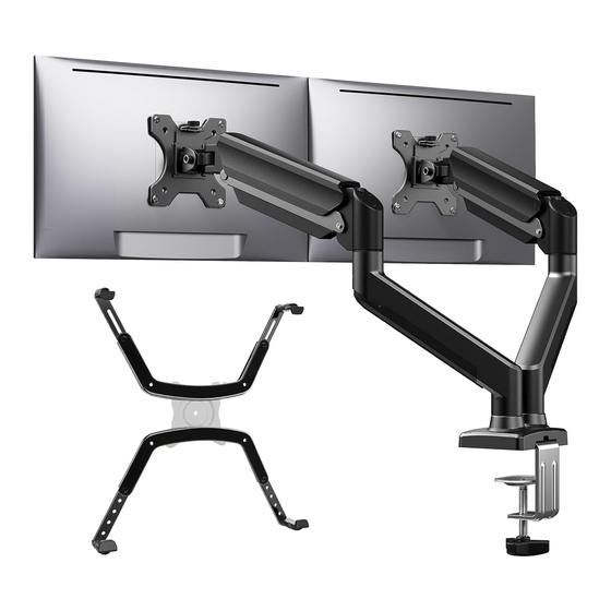
Page 4: Product Features
Product Features 180° 360° 360° +90°/-35° C-Clamp Mounting Grommet Mounting... - Page 5 TENSION ADJUSTMENT SHOULD BE DONE ONLY AFTER MONITOR INSTALLATION Attention DO NOT adjust tension without monitor attached. 1. Verify the weight of your monitor (including accessories) is between 4.4-22 lbs (2-10kg). Monitor weight information can be found in the monitor instruction manual or by contacting the manufacturer. 2.
- Page 6 Step 1 Supplied Parts and Hardware C-Clamp Bolt Base C-Clamp Brace 5/32” (4mm) 1/4” (6mm) Grommet Bolt Allen Key Allen Key Step 2 Supplied Parts and Hardware 5/32” (4mm) Upper Arm Section Lower Arm Section Allen Key Step 3 Supplied Parts and Hardware M4 x 12mm M4 x 30mm Monitor Plate...
- Page 7 L13mm 1/4” (6mm) Spacer Allen Key Step 5/7 Supplied Parts and Hardware 1/4” (6mm) Allen Key Step 9 Supplied Parts and Hardware 1/4” (6mm) Cable Cover Allen Key...
-
Page 8: Install The Base
Install the Base Step1 For C-Clamp Mounting For Grommet Mounting Skip to Page 07 For desk thickness: 0.39”-2.56” For desk thickness: (10-65mm) 0.39”-2.17” (10-55mm) Option A For C-Clamp Mounting 1/4” 1/4” (6mm) (6mm) 5/32” (4mm) - Page 9 Option B For Grommet Mounting CAUTION: Ensure the grommet bolt is screwed securely into the base. Separate the C-clamp and keep the clamp plate [06a] for later use. 1/4” (6mm) NOTE: If there is no grommet 2” (50mm) hole on the desk, you will need Electric Drill to drill one.
- Page 10 Step 2 Attach the Lower and Upper Arm Sections Attach the lower and upper arm sections [01] and [02], then tighten the set screws. Do not overtighten, as this may affect the rotation of the arm. NOTE: 5/32” (4mm) preattached cover should face down.
- Page 11 The hanging tab should be directed toward the top of the monitor. For Flat Back Monitor For Curved Back Monitor Step 4 Hang the Monitors on the Mount Loosen the knobs [S] on the monitor plate connectors, then attach the monitors and secure by tightening the knobs.
- Page 12 Step 5 Adjust Gas Spring Tension Hold the upper arm in a horizontal position. In this position, you can access the gas spring tension adjustment bolt to increase or decrease tension so the arm stays in position by itself. 1/4” Desk (6mm) CAUTION:...
- Page 13 Step 6 Adjust the Swivel Position of the Monitor Swivel the monitor to your desired position. Incorrect Correct Desk WARNING: Avoid the risk of tipping and falling. Do not position or swivel the monitor beyond the edge of the desk. Step 7 Adjust the Tilt Angle of the Monitor Adjust your monitor by gripping the monitor edges.
- Page 14 Step 8 Adjust the Rotation of the Monitor 360° Rotation Desk Route Cables Down the Arm Step 9 1/4” (6mm) 1/4” (6mm)
- Page 16 Thank you for choosing this ErGear product! At ErGear we strive to provide you with the best quality products and services in the industry. Should you have any issues, please don't hesitate to contact us. 1-800-651-9525 (US/CA) Mon–Fri, 8am–8pm (CST) 44-808-196-3875 (UK) Mon–Fri, 2pm–10pm (UTC)
Need help?
Do you have a question about the EGDS15B and is the answer not in the manual?
Questions and answers