Advertisement
Quick Links
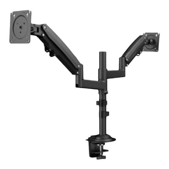
Monitor Desk Mount
Instruction Manual
V1.0
Model: EGDS6
Thank you for choosing this Ergear product! At Ergear we strive to
provide you with the best quality products and services in the
industry. Should you have any issues, please don't hesitate to contact
at support@ergear.com (US/CA/DE/UK/FR/IT/ES/AU)
Advertisement

Related Manuals for ErGear EGDS6


Summary of Contents for ErGear EGDS6
- Page 1 Instruction Manual V1.0 Model: EGDS6 Thank you for choosing this Ergear product! At Ergear we strive to provide you with the best quality products and services in the industry. Should you have any issues, please don't hesitate to contact at support@ergear.com (US/CA/DE/UK/FR/IT/ES/AU)
-
Page 2: Weight Restrictions
75mm/3 in.(W)x75mm/3 in.(H) If your Monitor VESA is greater than 100x100 mm/4x4 in. or less than VESA 75x75mm/3x3in., this mount is NOT compatible. If this desk mount is NOT compatible, please contact customer service at support@ergear.com to find a compatible product. -
Page 3: Product Features
Product Features 180° 360° 360° C-Clamp Mounting 1.0-3.2 in.(25-80mm) Grommet Mounting 0.8-3.5 in.(20-90mm) - Page 4 TENSION ADJUSTMENT SHOULD BE DONE ONLY AFTER MOUNT INSTALLATION Do not adjust tension without monitor 1. Ensure monitor has been attached to the mount. 2. Read your monitor box or manual to find out monitor net weight. 3. Ensure the net weight of monitor (including accessories) is between 4.4~26.5 Ibs (2-12 kg) per arm.
- Page 5 Before starting assembly, verify all parts are included and undamaged. Do not use damaged or defective parts. lf you require replacement parts, contact our customer service at support@ergear.com. • Please note: Not all hardware included in this package will be used.
- Page 6 Supplied Parts and Hardware for Step 2 Arm X2 Extension Arm x2 Locating Ring X2 (F) x1 (F) x1 1/8 in.(3mm) 5/32 in.(4mm) Plastic Sleeve X2 Allen Key Allen Key Supplied Parts and Hardware for Step 3 Bolt (A) Bolt (B-1) Spacer (B-2) M4x12mm (X8) M4x16mm (X8)
- Page 7 1. Install the Base A. For Clamp Mounting A-1 For Clamp Mounting Slide the cable clips [06] to pole assembly [05] and secure part [a] to Detach the c-clamp entirely pole assembly [05] Warning: Ensure bolts are secured firmly. 5/32 in. (4mm) Connect part [b] to part [a] according to the thickness of the desktop...
- Page 8 Secure the pole assembly to the desktop 1.0-3.1 in. (25-80mm) Warning: Ensure bolts are secured firmly. B. For Grommet Mounting Install the grommet bolt [D] to the bottom of pole assembly [05] Warning: Ensure bolts are secured firmly.
- Page 9 Secure the pole assembly to the desktop with grommet Warning: Ensure bolts are secured firmly. 2. Install the Arms ① ② Slide the extension arms [02] to the pole Fasten the locating ring [07] at your assembly [05], and attach the plastic desired height.
- Page 10 ③ ④ Secure the arms [01] to the extension Attach the arms [01] to the extension arms [02] by tightening the preassembled arms [02] set screw [S] using Allen key [F] 1/8 in. (3mm) Warning: Ensure bolts are secured firmly. Step 3 Attach Monitors to the Arms 3-1 Choose Proper bolts 3-2 Install Monitors to the Arms...
- Page 11 4. Adjust Gas Spring Tension Be sure to keep the arm in horizontal position during adjustment. Or else, it would be difficult to adjust the mount or damage the mount. 1. If the monitor can stay at the desired height by itself, no adjustment needed. 2.
-
Page 12: Tilt Adjustment
5. Rotation Restriction Proper usage directions Non-proper usage directions 6. Tilt Adjustment 13/64 in. (5mm) “+” Clockwise: Tighten “-” Counter-clockwise: Loosen Situation 1: If the monitor can stay at the desired tilt angle by itself, no adjustment needed. Situation 2: If the monitor can not stay at the desired tilt angle by itself, turn the bolt clockwise or counter-clockwise as shown until the monitor can stay at the desired tilt angle by itself. -
Page 13: Rotation Adjustment
7. Rotation Adjustment Rotation Only suitable for the monitors with the center of gravity in the center position 8. Route Cables along the Arms... - Page 14 Warning: Ensure bolts are secured firmly.
- Page 16 Thank you again choosing this Ergear product! All of us at Ergear do appreciate your product purchase. We hope that you are as happy with your product as we are designing and manufacturing it for you. We strive to provide you with the best quality products and services in the industry.
Need help?
Do you have a question about the EGDS6 and is the answer not in the manual?
Questions and answers