
Related Manuals for ErGear EGDS2


Summary of Contents for ErGear EGDS2
- Page 1 Desk Monitor Arm Instuction Manual EGDS2 Rev00(A) Technical Support: (US/CA) 1-800-651-9525 Mon–Fri, 8am–8pm (CST) (UK) 44-808-196-3875 Mon–Fri, 2pm–10pm (UTC) Other Info: support@ergear.com Website: https://ergear.com...
- Page 2 • Please carefully read all instructions before attempting installation. If you do not understand the instructions or have any questions or concerns, please contact our Technical Support at 1-800-651-9525 (US / CA), 44-808-196-3875 (UK) or Customer Service at support@ergear.com. CAUTION: Avoid potential injuries and property damage! •...
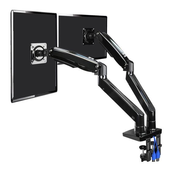
- Page 3 Product Features 360° 360° 180° +85°/ -30° 360° 21'' (533mm) C-Clamp Mounting for table edge 0.4 - 3.5 (10 - 90mm) ” Grommet Mounting for grommet bolt 0.4 - 3.5 (10 - 90mm) ”...
- Page 4 TENSION ADJUSTMENT SHOULD BE DONE ONLY AFTER MONITOR INSTALLATION Attention DO NOT adjust tension without monitor attached. 1. Verify the weight of your monitor (including accessories) is between 4.4 - 26.4 lbs (2 - 12 kg). 2. Monitor weight information can be found within its box or manual. 3.
- Page 5 Technical Support at 1-800-651-9525 (US / CA), 44-808-196-3875 (UK) or Customer Service at support@ergear.com. • NOTE: Not all hardware included in this package will be used. Step 1...
- Page 6 Medium Allen Key Locking Plate Butterfly Nut 5/32” (4mm) Step 3 Supplied Parts and Hardware Small Allen Key Arm Extender 1/8” (3mm) Step 4 Supplied Parts and Hardware Washer Bolt Large Allen Key Monitor Plate 16 x 8.2 x 1.5mm M8 x 38mm 3/16”...
- Page 7 Step 6 Supplied Parts and Hardware Large Allen Key 3/16” (5mm) Step 8 Supplied Parts and Hardware Large Allen Key 3/16” (5mm) Step 9 Supplied Parts and Hardware Small Allen Key 1/8” (3mm) Step 11 Supplied Parts and Hardware Large Allen Key 3/16”...
- Page 8 Step 1 Attach the USB Cable Option A: No USB Cable Option B: Route USB Cable Route USB cables under base as demonstrated in the following diagram. Use bolts [B] to attach USB pressure plate [A] to hold the USB cable in the base. Step 2 Attach to Desk Mounting Surface Option A: For Clamp Mounting...
- Page 9 2A-2 At an angle, guide the C-clamp [04] over the C-clamp brace [03] to desired position then straighten the C-clamp [04] to be vertical. Maximum thickness: 3.5” (90mm) 2A-3 After pushing the clamp fully onto the desk, rotate the knob until the C-clamp [04] is secured firmly to the underside of desktop.
- Page 10 Option B: For Grommet Mounting 2B-1 If a hole is needed for grommet installation, be sure to leave at least 2” from the edge of desktop and mark where the hole will be drilled. Use either a 3/8” or 3/8" - 1 1/16" 1 1/16”...
- Page 11 Step 3 Attach the Arm Sections 3-1 Push the arm extenders [05] into the base, and then the arms [06] onto the arm extenders [05]. 3-2 Tighten the set screws on both sides of the arm joints. Do not overtighten the set screws as this may affect the rotation of the arm.
- Page 12 Step 4 Attach the Monitor Plates Slide the monitor plates [07] sideways into the slot at the end of the arms [06]. Fasten with bolts [H] and washers [G].
- Page 13 Step 5 Attach the Monitors to the Arms Option A (For Flat Back Monitor) 5A-1 Thread two bolts [I] with washers [K] into the top holes until about 0.1-0.2" (3-5mm) of space is left between monitor back and washer. 0.1-0.2" (3-5mm) spacing left Turn clockwise to thread 5A-2 Hang the monitor from the monitor plate with the top two bolts [I] (see Fig.
- Page 14 Option B (For Curved Back Monitor) 5B-1 Slide the washers [K] and spacers [L] over the bolts [J]. Turn the top two bolts [J] CLOCKWISE until about 0.1-0.2" (3-5mm) of space is left between the washer [K] and the spacer [L]. 0.1-0.2"...
- Page 15 Step 6 Adjust the Gas Spring Tension 6-1 If the gas spring arm RISES with the monitor attached, hold the arm in a horizontal position while using the large Allen key [M3] to turn the adjustment bolt CLOCKWISE, REDUCING the arm tension. 6-2 If the gas spring arm LOWERS with the NOTE: Ensure the arm is held in a monitor attached, hold the arm in a...
- Page 16 Step 7 Rotation Restriction To ensure proper stability, do not position monitor behind base. Monitor and arms should remain over the desktop. Failure to do so may cause instability, resulting in property damage or injury. Incorrect orientation Correct orientation Step 8 Adjust the Monitor to Proper Tilt Angle 8-1 Slightly loosen the bolt with large Allen key [M3].
-
Page 17: Swivel Adjustment
Step 9 Swivel Adjustment Turn adjustment set screw CLOCKWISE to INCREASE the swiveling tension. Turn adjustment set screw COUNTER-CLOCKWISE to REDUCE the swiveling tension. WARNING: Do not overtighten or overloosen the bolts. 180° 180° 360° 360° 360° 360°... -
Page 18: Rotation Adjustment
Step 10 Rotation Adjustment Firmly hold monitor at edges and rotate from Landscape to Portrait mode. WARNING: Ensure bolts are secured firmly before rotation. 360° Rotation... - Page 19 Step 11 Route Cables along the Arm ③ ② ④ ① ⑤ ⑤ ① ③ ② ④...
- Page 20 Thank you for choosing this ErGear product! At ErGear we strive to provide you with the best quality products and services in the industry. Should you have any issues, please don't hesitate to contact us at Technical Support: (US/CA) 1-800-651-9525 Mon–Fri, 8am–8pm (CST)
Need help?
Do you have a question about the EGDS2 and is the answer not in the manual?
Questions and answers