
Related Manuals for Juniper EX4100-F- 24P/T


Summary of Contents for Juniper EX4100-F- 24P/T
- Page 1 Letter of Volatility IDENTIFICATION OF VOLATILE AND NON-VOLATILE STORAGE SANITIZATION OF SYSTEM COMPONENTS JUNIPER NETWORKS EX4100-F- 24P/T REVISION 1.0 December 27, 2022 Letter of Volatility...
-
Page 2: Table Of Contents
Letter of Volatility EX4100-F-24P/T 2/2/2023 TABLE OF CONTENTS Introduction ....................1 Purpose ....................1 Scope ....................1 Equipment Overview ................. 1 Identification of Chassis ..............1 Description of Field Replaceable Units (FRU) ........2 VOLATILE AND NON-VOLATILE MEMORIES ........2 3.1 Power Down and Removal of memory devices .......... -
Page 3: Introduction
In datacenters, EX4100-F-24P/T switches can be positioned as top-of-rack switches; the top devices in a rack to provide connectivity for all the devices in the rack. Juniper Networks SRX Series Ethernet Switches run Junos OS, which provides Layer2 and Layer3 switching, routing, and security services. -
Page 4: Description Of Field Replaceable Units (Fru)
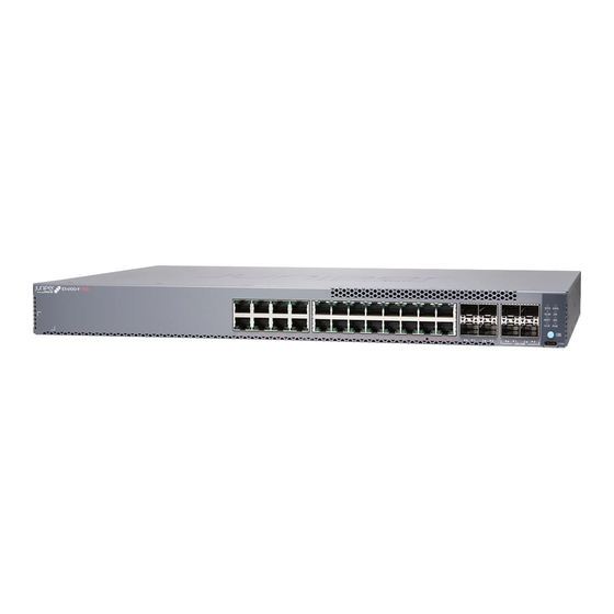
Letter of Volatility EX4100-F-24P/T 2/2/2023 Figure 2-1: EX4100-F-24P/T 2.2 Description of Field Replaceable Units (FRU) The power supply and transceivers are hot-swappable. You can remove and replace them without powering off the system or disrupting system functions. None of these components contain NV RAM. All NV RAM is either soldered or installed onto the system board. -
Page 5: Power Down And Removal Of Memory Devices
Letter of Volatility EX4100-F-24P/T 2/2/2023 3.1 POWER DOWN AND REMOVAL OF MEMORY DEVICES To ensure that no user data or system configurations remain reside on a EX4100-F-24P/T platform, the following steps must be performed: 1. Power must be removed from the system to clear all volatile storage. 2. -
Page 6: Figure 4 2: Top Cover Screws
Letter of Volatility EX4100-F-24P/T 2/2/2023 3. Remove Six screws on top side (figure 4-2) Figure 4-2: Top cover screws (Figure 4-3) Slide and lift to remove the Top cover. UNCLASSIFIED... -
Page 7: Figure 4 3: Side Screws Of Top Cover
Letter of Volatility EX4100-F-24P/T 2/2/2023 Figure 4-4: Side screws of Top Cover 4. Locate Volatile On Board memory (U14), and System CPLD (U33)on the Main Board (figure 4-5) Figure 4-5: Locate On Board Memory and System CPLD UNCLASSIFIED... -
Page 8: Figure 4 6: Locate Nv Storage (Eusb)
Letter of Volatility EX4100-F-24P/T 2/2/2023 5.Locate NON-Volatile storage on Main Board and RTC Battery (figure 4-6). Figure 4-6: Locate NV storage (eUSB & RTC Battery) 5. System Main Board ID EEPROM Top side (figure 4-7). Figure 4-7: Locate NIC System Mainboard EEPROM UNCLASSIFIED... -
Page 9: Follow The Assembly Procedure In Reverse Order To Assemble The Ex4100-F-24P/T Chassis
Letter of Volatility EX4100-F-24P/T 2/2/2023 6. Locate Uboot SPI FLASH (Bottom side) and Golden CPLD FW (Bottom Side ) from the Main Board Top Side (figure 4-8). Figure 4.8: CPU-CPLD and Uboot SPI Flash NOTE : Before removal, ensure J-TAC and the appropriate account team has been notified of your intentions.
Need help?
Do you have a question about the EX4100-F- 24P/T and is the answer not in the manual?
Questions and answers