Shure PSM900 - Wireless Personal Monitor System Manual
- User manual (65 pages) ,
- Instruction manual (60 pages) ,
- Quick start instructions (31 pages)
Advertisement
- 1 General Description
- 2 Components
- 3 Quickstart Instructions
- 4 Rack Unit Transmitter
- 5 Battery Life
- 6 Configuration Menu
- 7 Multiple System Setup
- 8 CueMode
- 9 Managing CueMode Mixes
- 10 Frequency Scan
- 11 Sync
- 12 MixMode
- 13 LOOP Applications
- 14 Squelch
- 15 Point-to-Point Wireless Audio
- 16 Specifications
- 17 Frequency Range and Transmitter Output Power
- 18 Furnished Accessories
- 19 Optional Accessories
- 20 IMPORTANT SAFETY INSTRUCTIONS
- 21 Documents / Resources
General Description
The Shure PSM 900 Wireless Personal Monitor System offers an unprecedented combination of superb audio quality, robust RF performance, and category-leading features for the most demanding professional applications. Patented Audio Reference Companding and advanced digital signal processing technology provide excellent stereo separation and audio clarity. Exceptional transmitter linearity vastly reduces frequency intermodulation, allowing more channels per frequency band. Patented CueMode technology enables the sound engineer to monitor different stage mixes with the touch of a button.
Features
Unparalleled Audio Quality
- Bodypack receivers with advanced digital signal processing technology deliver more headroom, improved stereo separation, and higher audio fidelity.
- Patented Audio Reference Companding offers natural and transparent sound.
- Available with Shure SE425 Sound Isolating earphones featuring dual high definition MicroDrivers for accurate and balanced audio response.
Robust RF Performance
- P9RA+ bodypack receivers offer enhanced signal reception and range.
- Precision front-end RF filtering significantly reduces RF interference for a cleaner, stronger RF signal, fewer dropouts, and fewer audible artifacts.
- Exceptional transmitter linearity vastly reduces frequency intermodulation and allows up to 20 compatible channels per frequency range.
- Automatic RF gain control prevents signal distortion due to RF overload before it can affect performance.
Category-Leading Setup and Operation Features
- CueMode allows monitoring of different stage mixes and storing of up to 20 separate channels on one bodypack for quick and easy reference.
- Front panel RF mute switch enables or disables RF transmission during setup.
- Scan and Sync scans the RF environment with the bodypack and assigns an identified group and channel to your system over wireless IR link.
- MixMode technology allows the bodypack user to combine two separate audio channels for simultaneous listening in both ears, or can transmit two independent IFB program feeds. Balance control on the bodypack adjusts the relative levels for each audio signal.
- Four-band parametric EQ gives the user the choice to adjust frequencies for a fully customized sound.
Advanced Rechargeability Options
- The SB900B lithium-ion rechargeable battery provides extended usage times and precise tracking of remaining life and charge cycle details.
- The SCB800 US eight bay charger brings up to eight SB900B batteries to full charge within two hours and has charge status LEDs for each battery.
- The SBC200 dual-docking charger works with SB900B, P3RA, P9RA+, P10R+, QLX-D Digital Wireless Systems, and ULX-D Digital Wireless Systems, available with and without power supply.
- The SBC220 networked dual-docking charger works with SB900B, PSM 300 (P3RA only), PSM 900 (P9RA+ only), PSM 1000 (P10R+ only), QLX-D Digital Wireless Systems, ULX-D Digital Wireless Systems, and Axient Digital (AD1 and AD2 only), available with and without power supply. When the SBC220 is connected to a network, battery information for each transmitter can be viewed remotely.
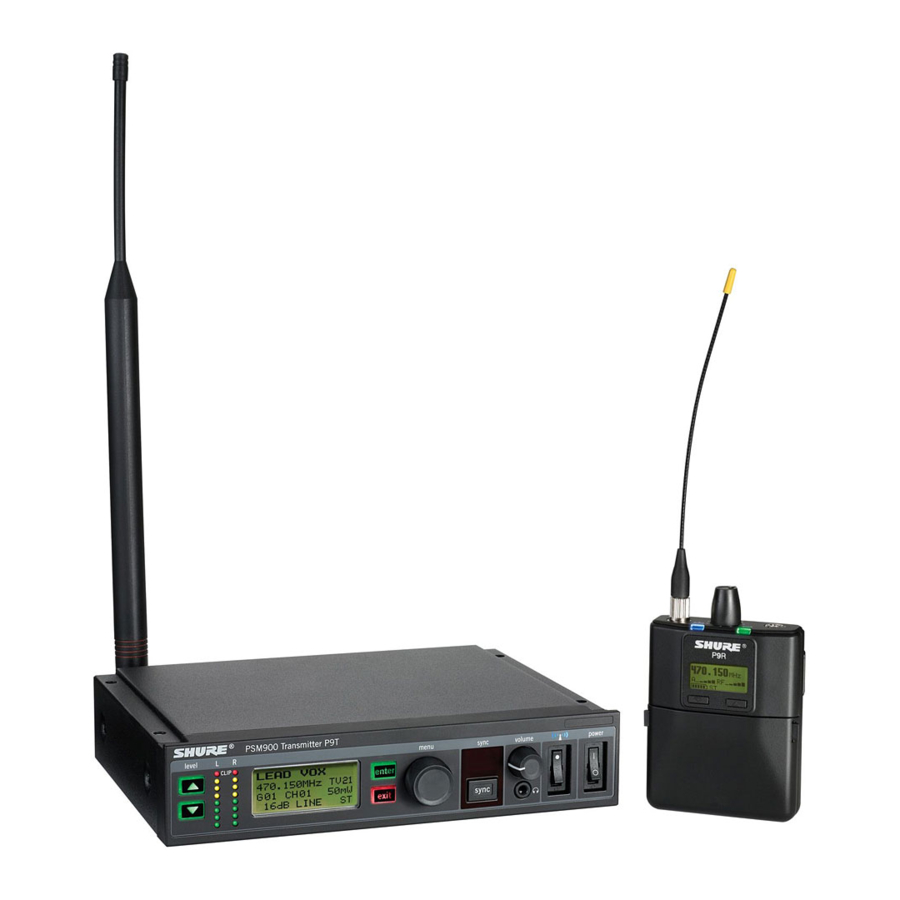
Components
- P9T: Rack Unit Transmitter
- P9RA+: Bodypack Receiver
- PS43: Power supply
- Protective bumpers with 8 screws

Rackmount supplies
- Short rack ear
- Long rack ear
- Link bar to mount to similar rack unit
- 2 antenna hole plugs
- 8 rack ear screws
- 4 rack mount screws with washers
- Extension cables and connectors for front-mounting antennas
Quickstart Instructions
Rack Mount Transmitter
- Connect to a power outlet using the supplied power adapter.
![]()
- Attach the supplied antennas to the antenna out BNC connectors.
![]()
- Connect the audio source, such as the output of a mixer, to the audio inputs. You can use both input jacks or choose either one for a mono source.
![]()
- For mono (one input), access the Audio menu and select Mono.
- Set the input sensitivity to match the source by selecting Audio INPUT from the LCD configuration menu: Aux (-10dBV) or Line (+4dBu).
- Make sure the RF switch is OFF. Turn the power ON.
![]()
- Adjust the audio source level so that, for the average input signal level, the top two yellow LEDs flicker and the lower LEDs are solid.
![]()
- If the red clip LED illuminates, the inputs are overdriven. Decrease the level using the ▼ ▲ buttons or change the input sensitivity to +4 dBu.
- If the signal level is too low, change the input sensitivity to –10 dBV


Bodypack

Insert batteries and attach antenna. Turn on using the volume knob. The battery light illuminates.
Installing Bodypack Antennas
Hand-tighten antennas until secure. Do not use tools.
Scan and Sync
- On the bodypack, press the scan button. The display flashes SYNC NOW.
![]()
- Align the IR windows on the bodypack and rack unit and press the sync button. The rack unit Level LEDs flash, and it displays SYNC SUCCESS.
![]()
- Turn the RF switch on. The blue RF LED illuminates on the bodypack to indicate that it is detecting the transmitter. The bodypack also displays the RF signal strength (RF).
![]()
Turn bodypack volume down before plugging in earphones.- Insert the earphones and slowly turn up the volume.
![]()


Rack Unit Transmitter
Front Panel Controls

- Input Level Control and Display
Use the ▼ ▲ buttons to adjust the audio so that, for the average input signal level, the top two yellow LEDs flicker and the lower LEDs are solid. The red clip LED indicates the inputs are overdriven. Reduce the level at the audio source or change the input sensitivity of the rack unit from the AUDIO > INPUT menu. - Status Display and Menu Controls
Use the enter and exit buttons and the menu wheel to access the configuration menu. Push the menu wheel to move the cursor to the next item. Turn the menu wheel to change a parameter—the enter button flashes. Press it to save the value. Press the exit button to cancel changes and return to the previous menu. - Synchronization Button
Press the sync button while rack unit and bodypack IR windows are aligned to transfer settings. - Headphone Monitoring
The volume control adjusts signal output to the 3.5 mm headphone jack. NOTE: it does not affect rear panel outputs. - RF switch
Mutes RF output. For setting up multiple systems or adjusting settings without transmitting unwanted RF or audio signals. - Power Button
Turns the unit on and off.
Rear Panel Connectors

- Power
Connect the transmitter to a power outlet using the supplied power adapter. - LOOP OUT
Sends a copy of the audio signal going into the transmitter to another device. See LOOP Applications. - Audio Inputs
Connect to balanced or unbalanced outputs. Use either connector for mono input. Accepts both 1/4 inch or male XLR connectors. - Antenna (BNC)
Attach supplied antenna. If you are rack mounting, use a front panel or remote mounting kit from Shure.
Configuration Menu
Note: Configuration menu items may vary with regional model variations.
RF Settings
RADIO
G
Sets the group number
CH
Sets the channel number
888.888MHz
Manual frequency selection
RF POWER
Select from 10, 50, or 100 mW (varies by region)
Audio Settings
AUDIO > MODE
Selects monitor mode
STEREO/MX
Transmits both channels
MONO
Transmits a mono signal to bodypack
AUDIO > INPUT
Sets nominal input level
LINE +4 dBu
line level
AUX 10dBV
aux level
Utilities and Display Settings
UTILITIES
EDIT NAME
Changes the name on the LCD display (this name is uploaded to the bodypack with sync)
DISPLAY
Changes the display format
CONTRAST
Changes the display contrast
CUSTOM GROUP
For creating custom frequency groups
UTILITIES > LOCK PANEL
Locks front panel controls. To unlock, press exit, select OFF, and press enter.
MENU+LEVEL
Locks menu and level controls.
MENU ONLY
Locks only the configuration menu (menu controls).
MENU+SWITCH
Locks all controls except for the level buttons (including the RF and power switches).*
ALL
Locks all controls (including the RF and power switches).*
*RF is automatically activated when locked. When you unlock the unit, RF and power turns off if the swithes are off.
UTILITIES > RX SETUP
These settings are sent to the bodypack during a sync (when the sync direction is from the transmitter). The default KEEP parameter will not change the bodypack settings.
LOCK
Lock bodypack
V LIMIT
Volume limiter
LIM VAL
Volume limiter value
MODE
Stereo (ST) or MixMode (MX)
BAL MX
CH. 1 (L) and CH. 2 (R) mix for MixMode
BAL ST
Left (L) and right (R) balance for stereo mode
HIBOOST
high frequency boost
UTILITIES > RESET SYSTEM
Returns all settings to the factory defaults
NO
Exit and do not reset system.
YES
Reset system settings.
Bodypack Receiver

- Power Switch and Volume Control
Turns the bodypack on and off and adjusts earphone volume. - 3.5 mm Earphone Jack
Insert earphones here. - Scan Button
Press the scan button to find an available frequency. Press and hold for two seconds to find the group with the most available channels. - IR Window
For transmitting settings between bodypack and rack unit. - Battery Compartment
Requires 2 AA batteries or Shure rechargeable battery. Open by pressing the latches on both sides and pulling. - Menu buttons
Use in conjunction with the ▼ ▲ buttons to access the configuration menus. - ▼ ▲ Buttons
Use to adjust the audio mix (in MixMode only), or in conjunction with the menu buttons to change settings. - LCD Screen
Displays current settings and menus. - Tri-Color Battery LED
Illuminates green, amber, or red to indicate battery power. When red, change battery immediately. - Blue RF LED
Indicates the bodypack is receiving a signal from the transmitter. - SMA Connector
For detachable antennas. - Removable AA Adapter
Remove to use with a Shure SB900B rechargeable battery.
Note: To remove adapter, open door and slide out. To reinstall adapter, place over the clip and press, there will be an audible click when seated.
Battery Life
| Battery Indicator | Tri-Color Battery LED | Approximate Hours Remaining (h: mm) | |||||
| Alkaline | Shure SB900B Rechargeable Battery | ||||||
| Volume Level | Volume Level | ||||||
| 4 | 6 | 8 | 4 | 6 | 8 | ||
 | Green | 6:00 to 3:50 | 4:20 to 2:45 | 3:15 to 2:05 | 8:00 to 3:45 | 6:45 to 3:45 | 6:00 to 3:45 |
 | Green | 3:50 to 2:50 | 2:45 to 2:00 | 2:05 to 1:30 | 3:45 to 2:45 | 3:45 to 2:45 | 3:45 to 2:45 |
 | Green | 2:50 to 1:15 | 2:00 to 1:00 | 1:30 to 0:50 | 2:45 to 1:45 | 2:45 to 1:45 | 2:45 to 1:45 |
 | Green | 1:15 to 0:25 | 1:00 to 0:20 | 0:50 to 0:20 | 1:50 to 0:55 | 1:50 to 0:55 | 1:50 to 0:55 |
 | Amber | 0:25 to 0:15 | 0:20 to 0:10 | 0:20 to 0:10 | 0:55 to 0:25 | 0:55 to 0:25 | 0:55 to 0:25 |
 | Red | < 0:15 | < 0:10 | < 0:10 | < 0:25 | < 0:25 | < 0:25 |
| Total Battery Life | 6:00 | 4:20 | 3:15 | 8:00 | 6:45 | 6:00 | |
Power-save mode: When there are no earphones plugged in for 5 minutes, the receiver enters power-save mode to preserve battery life. The LED slowly fades on/off in this mode and continues to display the color that represents the remaining battery life.
Note: Battery life using Energizer brand AA Alkaline batteries and the following conditions:
- Receiver audio set to V LIMIT = 0dB
- Transmitter audio INPUT set to Line+4 dBu and Level set to −9 dB
- Audio input to the transmitter: pink noise at +8.7 dBV
- Audio output at receiver: 115 dB SPL in ear with SE425 earphones (impedance at 22 Ώ) set at volume level 4.
Note: Using lower-impedance earphones or ones with different sensitivity, different battery types, and higher gain settings in the PSM system may cause the receiver battery life to be different than specified.
Pink noise is a signal with a frequency spectrum such that the power spectral density is inversely proportional to the frequency. In pink noise, each octave carries an equal amount of noise power.
Note: A Battery Hot warning indicates that transmitter battery needs to cool off. Otherwise, the transmitter will shut down. Let the device cool down and then consider swapping the transmitter battery to continue operation.
Identify any possible external heat sources to the transmitter and operate the transmitter away from those external heat sources.
All batteries should be stored and operated away from external heat sources in reasonable temperature conditions for best performance.
Configuration Menu

RF Settings
Access the following RF settings from the RADIO menu.
RADIO
G:
Group number. Each group contains channels selected to work well together in a single installation.
CH:
Channel number. Sets the receiver to a channel in the selected group.
888.888 MHz
Displays the frequency to which the receiver is set. Highlight and use the ▼ ▲ buttons to set to a specific frequency.
SQUELCH
Adjusts the squelch setting.
RF PAD
Attenuates antenna signals in 3 dB increments.
Audio Settings
Access the following audio settings from the Audio menu.
Output Mode (MODE)
STEREO
Receive left and right inputs as a stereo signal
MIXMODE
Set your receiver to combine the left and right channel for simultaneous listening in both ears or pan to listen to only the left or right channel
Four-Band Parametric Equalizer (EQ)
The parametric equalizer is divided into four frequency bands: LOW, LOW MID, HIGH MID, and HIGH. When the EQ is enabled, the following parameters are adjustable:
FREQUENCY
Select the center frequency of the band to boost/cut
Q
Adjusts the width and slope of the frequency band (measured in octaves)
GAIN
Adjustable in 2 dB increments from -6 dB (cut) to +6 dB (boost)
NOTE: HIGH and LOW are shelf filters, and therefore do not have adjustable Q widths. The HIGH shelf is fixed at 10 kHz; the LOW shelf is fixed at 100 Hz.

Volume Limiter (V LIM)
V LIM
Set a value (OFF to 48 dB, adjustable in 3 dB increments) to attenuate the highest possible volume level. Turning the volume knob through its entire range of motion still affects volume; the limit simply narrows the range of dB adjustment.
Note: The volume limit does not compress the audio signal.
Volume Lock (V LOCK)
P9RA+ and P10R+ only
ON
The volume is locked to the physical position of the volume knob
Input EQ Preset (EQPre)
Input EQ affects the signal after it is sent to the receiver, but before the headphone output, modifying the overall sound of the entire system.
Match (default)
Matches the frequency response of legacy PSM receivers, allowing for matched audio with mixed-inventory setups
Flat
Offers a flat frequency response curve
Off
Audio bypasses input EQ
Balance (BAL ST / BAL MIX)
▼ ▲ Buttons
Left and right balance for earphones when in stereo mode, or mix of left and right channel for MixMode
Utilities and Display Settings
Access the following settings from the UTILITIES menu.
UTILITIES
CUEMODE
Enters CUEMODE (to exit, press enter and select EXIT CUEMODE)
DISPLAY
Change the display settings on the bodypack
CONTRAST
Sets display brightness to high, low, or medium.
LOCK PANEL
Locks all controls except power and volume. To unlock, press exit, select OFF, and press enter.
BATTERY
Displays the following: Hrs: Min Left, temperature, Status, Cycle Count, and Health.
RESTORE
Returns receiver to factory default settings.
Multiple System Setup
When setting up multiple systems, designate a single bodypack to scan for available frequencies and download them to all the rack units.
The bodypack must be from the same frequency band as all the transmitters.
- Power on all the rack units. Turn off the RF. (This prevents them from interfering with the frequency scan.)
Note: Turn on all other wireless or digital devices as they would be during the performance or presentation (so the scan will detect and avoid any interferance they generate). - Use the bodypack to scan for a group by pressing and holding the scan button for two seconds. The bodypack displays the group and the number of available channels, and flashes SYNC NOW....
![]()
Note the number of available channels. If you have more rack units than available channels, eliminate potential sources of interference and try again, or call Shure Applications for assistance. - Sync the bodypack with the first rack unit by aligning the IR windows and pressing sync.
- Press scan again on the bodypack to find the next available frequency.
- Sync the bodypack with the next rack unit.
- Repeat with all the rack units.
- Sync each performer's bodypack to its respective rack unit by aligning the IR windows and pressing snyc. DO NOT press scan on the bodypacks.
- Turn on the RF on all rack units. The systems are ready to use.
CueMode
CueMode allows you to upload the name and frequency settings from multiple rack units and store them as a list on a single bodypack. You can then, at any time, scroll through that list to hear the audio mix from each transmitter, just as each performer does during a show.
CueMode lists are retained even if CueMode is exited, the bodypack is turned off, or batteries are removed.
Note: Set the channel frequency and assign display names for each transmitter before creating your CueMode list.
Adding Transmitters to the CueMode List
Note: The transmitter must be from the same frequency band as the bodypack.
- Open the battery door and press the enter button.
- From the main menu, scroll to UTILITIES and press enter. Select CueMode and press enter again.
- Align IR windows and press sync on the rack unit.
The LCD displays SYNC SUCCESS after frequency and name data are uploaded to the CueMode list. It also displays the CueMode number for that transmitter and the total number of transmitters. - Repeat the above step for each transmitter.
Note: Syncing while in CueMode does not change any of the settings on the bodypack.
Auditioning Mixes
- Enter CueMode from the UTILITIES menu.
- Use the ▼ ▲ buttons to scroll through your CueMode list to hear the mixes.
Exiting CueMode
Exit CueMode by pressing enter and selecting EXIT CUEMODE.
Managing CueMode Mixes
While in Cue Mode, you can access the following menu by pressing enter:
REPLACE MIX
Select and press sync on a rack unit to upload new data for the current mix (for example, if you have changed the transmitter frequency).
DELETE MIX
Removes the selected mix.
DELETE ALL
Removes all mixes.
EXIT CUEMODE
Exits CueMode and returns the bodypack to the previous frequency setting.
Frequency Scan
Use a frequency scan to analyze the RF environment for interference and identify available frequencies.
- Channel Scan Press the scan button on the bodypack. Finds the first available channel.
- Group Scan Press and hold the scan button for two seconds. Finds the group with the greatest number of available channels. (Each group contains a set of frequencies that are compatible when operating multiple systems in the same environment.)
Note: When performing a frequency scan:
- Turn off the RF on the transmitters for the systems you are setting up. (This prevents them from interfering with the frequency scan.)
- Turn on potential sources of interference such as other wireless systems or devices, computers, CD players, large LED panels, effects processors, and digital rack equipment so they are operating as they would be during the presentation or performance (so the scan will detect and avoid any interference they generate).
Sync
You can transfer frequency settings in either direction: from the bodypack to the rack unit, or from the rack unit to the bodypack.
Note: You can also choose to transfer other settings to the bodypack during a sync, such as lock or mode settings, using the Sync > RxSetup menu on the rack transmitter.
Downloading settings from the bodypack
- Press the scanbutton on the bodypack.
- Align the IR windows and press the syncbutton from the rack transmitter LCD menu while the bodypack display is flashing "SYNC NOW".
The level LEDs on the rack unit flash.
Sending settings to the bodypack
- Press the Sync button on the rack transmitter to access the sync menu.
- Align the IR windows.
When properly aligned the IR window on the transmitter illuminates. - Press Sync to transfer settings.
The blue LED on the bodypack flashes.
MixMode
Some performers need to hear more of their own voice or instrument, while others want to hear more of the band. With MixMode, the performer creates their own mix using the balance control ( ▼ ▲ buttons) on the bodypack.
To use MixMode, send a solo mix of the performer to the L/CH1 input on the transmitter, and send a band mix to the R/CH2 input.
Set the performer's bodypack for MixMode. The bodypack combines the two signals and sends them to both earphones, while the balance control on the bodypack adjusts the relative levels for each.
For IFB applications, send two independent program feeds into the L/CH1 and R/CH2 input of the transmitter. With MixMode, the director or broadcast talent can listen to either feed using the balance control ( ▼ ▲ buttons) on the bodypack to pan to either audio signal.
LOOP Applications
Use LOOP OUT L (left) and R (right) outputs to send a copy of the audio signal going into the transmitter to other devices. Following are a few of the many applications for these outputs.
Note: The input level control and the input pad do not affect the LOOP OUT signals.
MixMode for Multiple Systems
Configure each system for MixMode. From the mixing console, send a mix of the whole band to input 2 of the first transmitter. Connect the LOOP OUT R output to the R/CH2 input of the next transmitter. Continue the chain with all the transmitters.
Next, create solo mixes for each performer. Send each mix to input 1 of the transmitter for that performer.
Floor Monitors
Send the audio from the LOOP outputs to onstage loudspeakers. The bodypack and the onstage monitors receive the same audio signals.
Note: The LOOP audio outputs will not drive passive loudpeakers, and must be sent to a power amplifier or an active loudspeaker.
Recording Devices
To record a performance, connect the LOOP outputs to the inputs of a recording device.
Squelch
Squelch mutes audio output from the bodypack when the RF signal become noisy. While squelch is activated, the blue LED on the bodypack turns off.
For most installations, squelch does not need adjustment, and it keeps the performer from hearing hiss or noise bursts if the
RF signal becomes compromised. However, in congested RF environments or in close proximity to sources of RF interference (such as large LED video panels), the squelch may need to be lowered to prevent excessive audio dropouts. With lower squelch settings, the performer may hear more noise or hiss, but will experience fewer audio dropouts.

Before lowering squelch, first try to eliminate the problem by finding the best set of frequencies for your installation and removing potential sources of interference.

Turning off or lowering the squelch setting can increase the noise level and cause discomfort to the performer:
- Do not lower the squelch setting unless absolutely necessary.
- Turn earphone volume to the lowest setting before adjusting squelch.
- Do not change the squelch setting during a performance.
- Turn up the transmitter level setting to make noise or hiss less noticeable.
| Squelch Settings | ||
| HIGH (NORMAL) | Default factory setting. | |
| MID | Moderately decreases the signal-to-noise ratio required to squelch the receiver. | |
| LOW | Greatly decreases the noise squelch threshold. | |
| PILOT ONLY* |  | Turns off noise squelch leaving only pilot squelch on. |
| NO SQUELCH* |  | Turns off noise and pilot tone squelch. (Sometimes used as a debugging tool by monitor engineers or RF coordinators to "listen" to the RF environment.) |
| * Symbol appears in dis play window. | ||
Point-to-Point Wireless Audio

Use PTP mode to allow a P9T to transmit to a UHF-R receiver. This allows a transmitter and receiver setup where both units are racked and powered by AC.
For more information visit: www.shure.com/americas/products/personal-monitor-systems
Specifications
PSM 900
RF Carrier Range 470–952 MHz
varies by region
| Compatible Frequencies | |
| Per band | 20 |
Tuning Bandwidth
36–40 MHz
Note: varies by region
Operating Range
environment dependent
90 m ( 300 ft)
Stereo Separation
60 dB
Audio Frequency Response
35 Hz–15 kHz (±1 dB)
Signal-To-Noise Ratio
A-Weighted
90 dB (typical)
Total Harmonic Distortion
ref. ±34 kHz deviation @1 kHz
<0.8% (typical)
Companding
Patented Shure Audio Reference Companding
Spurious Rejection
ref. 12dB SINAD
>80 dB (typical)
Frequency Stability
±2.5 ppm
MPX Pilot Tone
19 kHz (±0.3 kHz)
Modulation
FM*, MPX Stereo
*ref. ±34 kHz deviation @1 kHz
Operating Temperature
-18°C to +57°C
P9T
RF Output Power
selectable: 10, 50, 100 mW (+20 dBm)
RF Output Impedance
50 Ω (typical)
Net Weight
850 g
Dimensions
42 x 197 x 177 mm, H x W x D
Power Requirement
15V DC, 415 mA, typical
Audio Input
Connector Type
Combination XLR and 6.35 mm (1/4") TRS
| Polarity | |
| XLR | Non-inverting (pin 2 positive with respect to pin 3) |
| 6.35 mm (1/4") TRS | Tip positive with respect to ring |
Configuration
Electronically balanced
Impedance
70.2 kΩ (actual)
Nominal Input Level
switchable: +4 dBu, –10 dBV
| Maximum Input Level | |
| +4 dBu | +29.2 dBu |
| 10 dBV | +12.2 dBu |
| Pin Assignments | |
| XLR | 1=ground, 2=hot, 3=cold |
| 6.35 mm (1/4") TRS | Tip=hot, Ring=cold, Sleeve=ground |
Phantom Power Protection
Up to 60 V DC
Audio Output
Connector Type
6.35 mm (1/4") TRS
Configuration
Electronically balanced
Impedance
Connected directly to inputs
P9RA+
Front-End RF Filtering
–3 dB at 30.5 MHz from the center frequency of each band
Active RF Gain Control
31 dB
Adjusts RF sensitivity to provide more RF dynamic range
RF Sensitivity
at 20 dB SINAD
2.2 µV
Image Rejection
>90 dB
Adjacent Channel Rejection
>70 dB
Latency
0.37ms
Squelch Threshold
22 dB SINAD (±3 dB)
default setting
Intermodulation Attenuation
>70 dB
Blocking
>80 dB
Audio Output Power
1kHz @ 1% distortion, peak power, @16Ω
100 mW (per output)
4-band Parametric EQ
9.5 Ω
| High Boost | |
| Low Shelf | Selectable Gain: ±2 dB, ±4 dB, ±6 dB @ 100 Hz |
| Low Mid | Selectable Gain: ±2 dB, ±4 dB, ±6 dB at 160 Hz, 250 Hz, 400 Hz, 500 Hz, 630 Hz Selectable Q: 0.7, 1.4, 2.9, 5.0, 11.5 |
| High Mid | Selectable Gain: ±2 dB, ±4 dB, ±6 dB at 1 kHz, 1.6 kHz, 2.5 kHz, 4 kHz, 6.3 kHz Selectable Q: 0.7, 1.4, 2.9, 5.0, 11.5 |
| High Shelf | Selectable Gain: ±2 dB, ±4 dB, ±6 dB @ 10 kHz |
Volume Limiter
Selectable: OFF (0 dB) to 48 dB in 3 dB steps
Volume Lock
Selectable: 0 dB to 70 dB
Limits volume adjustment knob. Selected value analogous to volume knob increment.
Net Weight
154 g (Without Battery)
Dimensions
83 x 65 x 22 mmH x W x D
Battery Life
4–6 hours (continuous use) AA batteries
Frequency Range and Transmitter Output Power
| Band | Range | Output |
| G6 | 470 –506 MHz | 10/50/100 mW |
| G6E | 470–506 MHz | 10/50 mW (Below 50 mW ERP) |
| G6J | 470–506 MHz | 6/10 mW |
| G14 | 506–542 MHz | 10 mW |
| G14J | 506–542 MHz | 6/10 mW |
| G62 | 510–530 MHz | 10/50 mW |
| G7 | 506–542 MHz | 10/50/100 mW |
| G7E | 506–542 MHz | 10/50 mW |
| G7Z | 518–542 MHz | 10/50/100 mW |
| H21 | 542–578 MHz | 10**/50/100 mW |
| K1 | 596–632 MHz | 10/50/100 mW |
| K1E | 596–632 MHz | 10 mW |
| K1J | 596–632 MHz | 6/10 mW |
| L6 | 656–692 MHz | 10/50/100 mW |
| L6E | 656–692 MHz | 10/50 mW (Below 50 mW ERP) |
| L6J | 656–692 MHz | 6/10 mW |
| P7 | 702–742 MHz | 10/50/100 mW |
| Q12 | 748–758 MHz | 10/50 mW |
| Q15 | 750–790 MHz | 10/50/100 mW |
| R21 | 794–806 MHz | 10 mW |
| X7 | 925–937.5 MHz | 10 mW |
| X1 | 944–952 MHz | 10/50/100 mW |
| X55 | 941–960 MHz | 10/50/100 mW |
NOTE: This Radio equipment is intended for use in musical professional entertainment and similar applications. This Radio apparatus may be capable of operating on some frequencies not authorized in your region. Please contact your national authority to obtain information on authorized frequencies and RF power levels for wireless microphone products.
Note: Frequency bands might not be available for sale or authorized for use in all countries or regions.
Furnished Accessories
| Omnidirectional Whip Antenna, Yellow Tip (470-542 MHz) | UA700 |
| Omnidirectional Whip Antenna, Black Tip (596-692 MHz) | UA720 |
| Omnidirectional Whip Antenna, Blue Tip (670-830 MHz) | UA730 |
| Omnidirectional Whip Antenna, Red Tip (830-952 MHz) | UA740 |
| 1/2 Wave Omnidirectional Receiver Antenna for improved wireless signal reception | UA8 |
| Antenna extension cables (2) | 95B9023 |
| Carrying/Storage Bag | 95A2313 |
| Rackmount Bracket, Long | 53A38729 |
| Short Rack Bar | 53A38728 |
| Link Bars (Bracket) | 53B8443 |
| Hardware Kit (Rackmounting Screws) | 90AR8100 |
| Bumper Kit | 90B8977 |
| Power Supply | PS43 |
Optional Accessories
| Passive Directional Antenna 470-952 MHz. Includes 10 foot BNC to BNC cable. | PA805SWB |
| PWS Helical Antenna, 480-900 MHz | HA-8089 |
| PWS Domed Helical Antenna, 480-900 MHz | HA-8091 |
| Helical Antenna, 944-954 MHz | HA-8241 |
| Wideband Omnidirectional Antenna (470-1100 MHz) | UA860SWB |
| 2 ft. BNC-BNC Coaxial Cable | UA802 |
| 6 foot (1.8m) BNC to BNC Coaxial Cable for Remote Antenna Mounting for ULX Wireless System | UA806 |
| 25 ft. BNC-BNC Coaxial Cable | UA825 |
| 50 ft. BNC-BNC Coaxial Cable | UA850 |
| 100 ft. BNC-BNC Coaxial Cable | UA8100 |
| 4 -to -1 antenna comber with power distribution to 4 transmitters (better RF perfor mance and eliminates need for external power supply) | PA421B |
| 8-to-1 antenna combiner for better RF performance | PA821B |
| Coiled IFB Earphone Cable for Shure Earphones | EAC-IFB |
IMPORTANT SAFETY INSTRUCTIONS
- READ these instructions.
- KEEP these instructions.
- HEED all warnings.
- FOLLOW all instructions.
- DO NOT use this apparatus near water.
- CLEAN ONLY with dry cloth.
- DO NOT block any ventilation openings. Allow sufficient distances for adequate ventilation and install in accordance with the manufacturer's instructions.
- DO NOT install near any heat sources such as open flames, radiators, heat registers, stoves, or other apparatus (including amplifiers) that produce heat. Do not place any open flame sources on the product.
- DO NOT defeat the safety purpose of the polarized or grounding type plug. A polarized plug has two blades with one wider than the other. A grounding type plug has two blades and a third grounding prong. The wider blade or the third prong are provided for your safety. If the provided plug does not fit into your outlet, consult an electrician for replacement of the obsolete outlet.
- PROTECT the power cord from being walked on or pinched, particularly at plugs, convenience receptacles, and the point where they exit from the apparatus.
- ONLY USE attachments/accessories specified by the manufacturer.
- USE only with a cart, stand, tripod, bracket, or table specified by the manufacturer, or sold with the apparatus. When a cart is used, use caution when moving the cart/apparatus combination to avoid injury from tip-over.
![]()
- UNPLUG this apparatus during lightning storms or when unused for long periods of time.
- REFER all servicing to qualified service personnel. Servicing is required when the apparatus has been damaged in any way, such as power supply cord or plug is damaged, liquid has been spilled or objects have fallen into the apparatus, the apparatus has been exposed to rain or moisture, does not operate normally, or has been dropped.
- DO NOT expose the apparatus to dripping and splashing. DO NOT put objects filled with liquids, such as vases, on the apparatus.
- The MAINS plug or an appliance coupler shall remain readily operable.
- The airborne noise of the Apparatus does not exceed 70dB (A).
- Apparatus with CLASS I construction shall be connected to a MAINS socket outlet with a protective earthing connection.
![burn hazard]()
![shock hazard]()
To reduce the risk of fire or electric shock, do not expose this apparatus to rain or moisture.- Do not attempt to modify this product. Doing so could result in personal injury and/or product failure.
- Operate this product within its specified operating temperature range.


LISTENING TO AUDIO AT EXCESSIVE VOLUMES CAN CAUSE PERMANENT HEARING DAMAGE. USE AS LOW A VOL UME AS POSSIBLE. Over exposure to excessive sound levels can damage your ears resulting in permanent noise-induced hearing loss (NIHL). Please use the following guidelines established by the Occupational Safety Health Administration (OSHA) on maximum time exposure to sound pressure levels before hearing damage occurs.
| 90 dB SPL at 8 hours | 95 dB SPL at 4 hours | 100 dB SPL at 2 hours | 105 dB SPL at 1 hour |
| 110 dB SPL at ½ hour | 115 dB SPL at 15 minutes | 120 dB SPL Avoid or damage may occur | |
This product is intended for professional use only. This product should only be sold through professional sales channels.
HEARING PRECAUTIONS
 | To prevent possible hearing damage, do not listen at high volume levels for long periods. |
SAFETY PRECAUTIONS
The possible results of incorrect use are marked by one of the two symbols—"WARNING" and "CAUTION"—depending on the imminence of the danger and the severity of the damage.
 | Ignoring these warnings may cause severe injury or death as a result of incorrect operation. |
 | Ignoring these cautions may cause moderate injury or property damage as a result of incor rect operation. |


- If water or other foreign objects enter the inside of the device, fire or electric shock may result.
- Do not attempt to modify this product. Doing so could result in personal injury and/or product failure.
Battery packs shall not be exposed to excessive heat such as sunshine, fire, or the like.
- Never disassemble or modify the device, as failures may result.
- Do not subject to extreme force and do not pull on the cable or failures may result.
- Keep the product dry and avoid exposure to extreme temperatures and humidity.

Documents / Resources
References
Download manual
Here you can download full pdf version of manual, it may contain additional safety instructions, warranty information, FCC rules, etc.
Download Shure PSM900 - Wireless Personal Monitor System Manual
Advertisement


Need help?
Do you have a question about the PSM900 and is the answer not in the manual?
Questions and answers