Shure ANIUSB-Matrix - Audio Network Interface Manual
- User manual (81 pages) ,
- Manual (32 pages) ,
- User manual (31 pages)
Advertisement
- 1 Getting Started
- 2 Hardware and Installation
- 3 What's in the Box
- 4 Controlling Devices with Shure Designer Software
- 5 Use Designer's Optimize Workflow
- 6 How to Update Firmware Using Designer
- 7 Connections and Signal Flow
- 8 Mute Sync
- 9 Overview of Shure Conferencing Devices
- 10 Audio Settings
- 11 Matrix Mixer
- 12 Using Call Status
- 13 Encryption
- 14 Networking and Dante
- 15 Using Command Strings
- 16 Reset
- 17 Troubleshooting
- 18 Event Log
- 19 Contact Customer Support
- 20 Specifications
- 21 Optional Accessories and Replacement Parts
- 22 Safety Information
- 23 Documents / Resources
Getting Started
To control the ANIUSB-MATRIX, use Shure Designer software. After completing this basic setup process, you should be able to:
- Control the ANIUSB-MATRIX in Designer
- Route audio to the ANIUSB-MATRIX in Designer
- Use the matrix mixer to route audio signals
Before you get started, you'll need:
- Cat5e (or better) Ethernet cable
- Network switch that provides Power over Ethernet (PoE)
- Shure Designer software installed on a computer. Download at www.shure.com.
Connect to a Network and Discover in Designer
- Connect the ANIUSB-MATRIX to a PoE port on the network switch using Cat5e (or better) cable.

- Connect your computer running Designer to the network switch.
- Open Designer, and check that you're connected to the correct network in Settings.
- Click Online devices. A list of online devices appears.
- To identify devices, click the product icon to flash the lights on a device.

Route Audio and Apply DSP
The easiest way to route audio and apply DSP is with Designer's Optimize workflow. Optimize automatically routes audio signals, applies DSP settings, turns on mute synchronization, and enables LED logic control for connected devices.
For this example, we'll connect an MXA310 table array microphone.
- Go to My projects > New to create a new project.
- Select New > Room (live) to create a new room. Any online devices appear in the list. Drag and drop the ANIUSBMATRIX and MXA310 to add them to your room.
- Select Optimize.
- Check the audio routes and settings to make sure they fit your needs. You might need to:
- Delete unnecessary routes.
- Fine-tune DSP blocks as needed.
- Test and adjust microphone coverage.
You can also route audio manually in Designer outside of the Optimize workflow, or use Dante Controller.
Configure Audio
The final configuration steps vary depending on what other devices you connect to the ANIUSB-MATRIX.
- Connect other analog and USB devices to the ANIUSB-MATRIX. If you have a computer with videoconferencing software, connect it to the USB port.
- Go to Matrix mixer to route audio between ANIUSB-MATRIX inputs and outputs. You can send a single input to many outputs or vice versa. To send audio from the MXA310 to the computer, check the box where Dante Input 1 and USB Output intersect.

- Perform a sound check and adjust input and output levels in Designer.
- Apply equalization (EQ) as needed to improve speech clarity.

General Description
The ANIUSB-MATRIX Audio Network Interface provides connections for USB, Dante, and analog audio sources. Collaborate and connect with all audio devices on a single network, with support for wireless microphones, computers, mobile devices, video codecs, and loudspeaker systems. Connect with a single network cable to receive audio and power through Power over Ethernet (PoE). Use Shure Designer software to control audio and network settings from any computer connected to the same network.
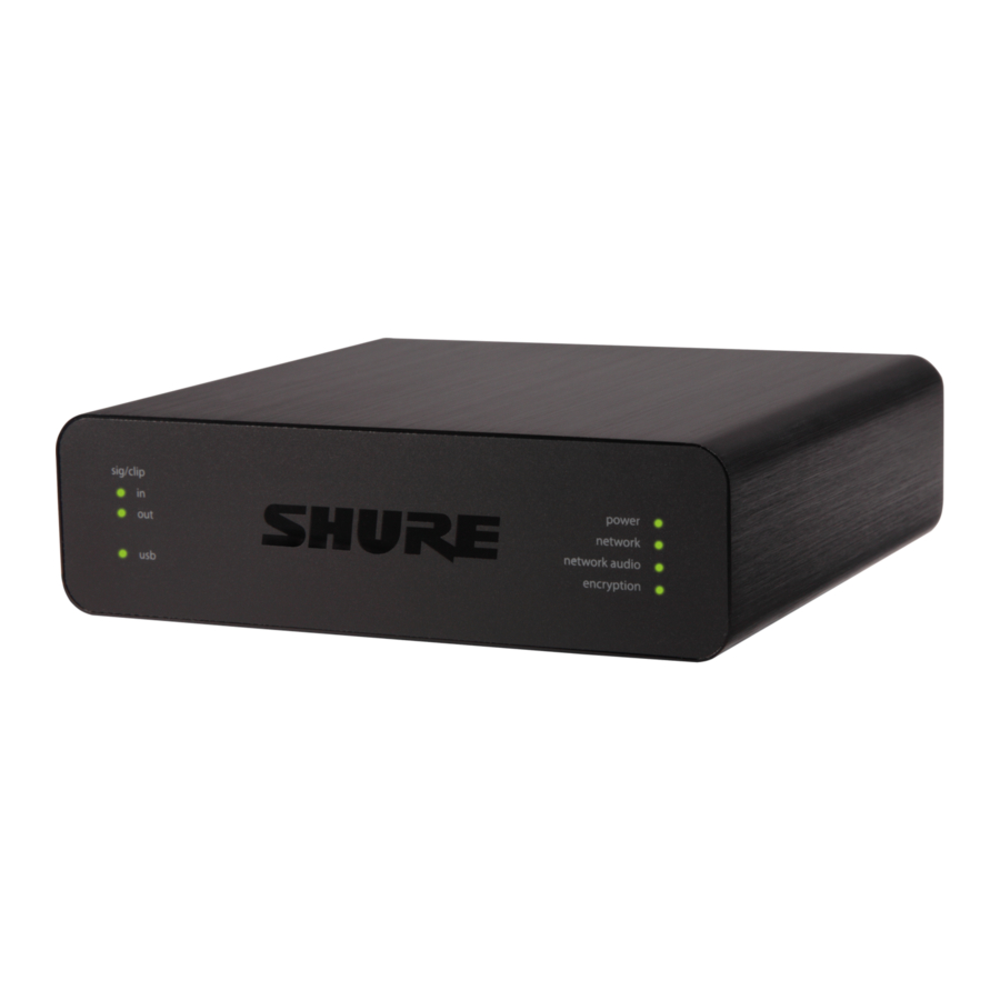
Hardware and Installation
Rear Panel

- Level Indicators (Signal/Clip)
Tri-color LEDs indicate the audio signal level for the analog channels and connectivity status for the USB channel. Adjust output levels in Shure Designer software to avoid clipping.
| Analog Input/Output | |
| LED State | Audio Signal Level |
| Off | less than -60 dBFS |
| Green | -59 dBFS to -24 dBFS |
| Yellow | -23 dBFS to -1 dBFS |
| Red | 0 dBFS or more |
| USB Audio | |
| LED State | Status |
| Off | No USB device connected |
| Green | USB device operating successfully |
| Red (flashing) | Problem detected with connected USB audio device |
Note: The input and output LEDs stay off when metering is set to Post-gain.
- Audio Input (Block Connector)
| Block Pin Assignments: | |
 | Audio + |
 | Audio - |
 | Audio ground |
- Chassis Ground Screw
Provides an optional connection for microphone shield wire to chassis ground. - Audio Output (Block Connector)
Balanced audio output connects to an analog device. Set the output level in Shure Designer software to match the input sensitivity of the analog device.
Note: See front panel labels for block connector assignments. - USB Port
Connects to a computer to send and receive any combination of input and output audio channels. - LED Indicators
Power: Power over Ethernet (PoE) present
Note: Use a PoE injector if your network switch does not supply PoE.
Network: Network connection active
Network Audio: Dante audio present on the network
Note: Error details are availble in the event log in Shure Designer software
| Network Audio LED Behavior | |
| LED Status | Activity |
| Off | No active signal |
| Green | Device is operating successfully |
| Red | Error has occurred. See event log for details. |
| Encryption: | |
| LED Status | Activity |
| Off | Audio not encrypted |
| Green | Successful encrypted audio connection with another device |
| Red | Encryption error. Possible causes: Encryption is enabled on one device and not on another Passphrase mismatch |
- Dante Network Port
Connects to a network switch to receive Dante audio, Power over Ethernet (PoE), and data from the control software. - Reset Button
Resets the device settings back to the factory default.
Power Over Ethernet (PoE)
This device requires PoE to operate. It is compatible with both Class 0 and Class 3 PoE sources.
Power over Ethernet is delivered in one of the following ways:
- A network switch that provides PoE
- A PoE injector device
Installation and Rack Mounting
Two mounting solutions are available for installing the Audio Network Interface:
CRT1 19" Rack Tray (optional accessory): Supports up to 3 devices; mountable in a rack or under a table
Single-unit Mounting Tray (included accessory): Supports a single device for mounting under a table
Securing the Devices
Use the included screws from the mounting hardware kit to secure the Audio Network Interfaces. Audio Network Interfaces can be mounted to face either direction. Insert the screws from the bottom in the appropriate holes, according to the following diagrams:

Align the holes as shown for securing a single device in the single-unit mounting tray

Align the holes as shown for securing up to 3 devices in the 19" rack tray.
Rack Ear Configuration
A combination of up to 3 Audio Network Interfaces can be mounted in a single 19-inch rack space. The adjustable rack ears support mounting in a standard equipment rack or underneath a table.
Standard 19 inch Rack Mount
- Align the ears with the mounting holes pointed forward.
- Install the 3 screws that hold the ear to the tray as shown.


Under-Table Mounting
- Align the ears with the mounting holes pointed upward.
- Install the 3 screws that hold the ear to the tray as shown.


Installing Underneath a Table
- Hold the tray in the desired location under a table.
- Use a pencil to mark the location of the mounting holes on the table.
- Drill 4 holes for the screws. The diameter of the holes in the tray are 7.1 mm.
- Install the components into the tray.
- Install with 4 screws to secure the tray underneath the table.
Device Identification
To identify the hardware by flashing the lights, select the Identify button in the device options section.
What's in the Box
| KIT, HARDWARE, ANIUSB-MATRIX | 90A33522 |
| Mounting Bracket (1/3 rack unit) | 53A27742 |
Note: USB cable not included.
Controlling Devices with Shure Designer Software
To control this device's settings, use Shure Designer software. Designer enables integrators and system planners to design audio coverage for installations using MXA microphones and other Shure networked devices.
To access your device in Designer:
- Download and install Designer on a computer connected to the same network as your device.
- Open Designer, and check that you're connected to the correct network in Settings.
- Click Online devices. A list of online devices appears.
- To identify devices, click the product icon to flash the lights on a device. Select your device in the list and click Configure to control device settings.
Learn more at shure.com/designer.
You can also access device settings using Shure Web Device Discovery.
Use Designer's Optimize Workflow
Designer's optimize workflow speeds up the process of connecting systems with at least 1 microphone and 1 audio processor. Optimize also creates mute control routes in rooms with MXA network mute buttons. When you select Optimize in a room, Designer does the following:
- Creates audio routes and mute control routes
- Adjusts audio settings
- Turns on mute synchronization
- Enables LED logic control for applicable devices
The settings are optimized for your particular combination of devices. You can customize settings further, but the optimize workflow gives you a good starting point.
Compatible devices:
- MXA920
- MXA910
- MXA710
- MXA310
- P300
- IntelliMix Room
- ANIUSB-MATRIX
- MXN5-C
- MXA Network Mute Button
To use the optimize workflow:
- Place all relevant devices in a room.
- Select Optimize. Designer optimizes microphone and DSP settings for your equipment combination.
If you remove or add devices, select Optimize again.
After optimizing a room, check and adjust settings to fit your needs. You may need to:
- Delete unnecessary routes.
- Check levels and adjust gain.
- Check that AEC reference signals are correctly routed.
- Fine-tune DSP blocks as needed.
How to Update Firmware Using Designer
Applies to Designer 4.2 and newer.
Before setting up devices, check for firmware updates using Designer to take advantage of new features and improvements. You can also install firmware using Shure Update Utility for most products.
To update:
- Open Designer. If there's new firmware that you haven't downloaded yet, Designer shows a banner with the number of updates available. Click to download firmware.
- Go to Online devices and find your devices.
- Choose a firmware version for each device from the Available firmware column. Make sure that no one is editing device settings during an update.
- Select the checkbox next to each device you plan to update and click Update firmware. Devices may disappear from Online devices during an update. Don't close Designer while updating firmware.
Firmware Versioning
When updating firmware, update all hardware to the same firmware version to ensure consistent operation.
The firmware of all devices has the form of MAJOR.MINOR.PATCH (e.g., 1.2.14). At a minimum, all devices on the network, must have the same MAJOR and MINOR firmware version numbers (e.g., 1.2.x).
Differences Between 3.x and 4.x Firmware
Support for Dante Domain Manager
- You can now add the ANIUSB-MATRIX to domains in Dante Domain Manager software.
Audio Encryption Improvements
- Firmware 4.x and newer has improved audio encryption, so make sure to update all Shure devices using encryption to the same major firmware version.
Web Applications Removed
- With firmware 4.x and newer, Shure Designer software is the only way to control the ANIUSB-MATRIX.
- You can access basic settings for the device by opening it from the Shure Web Device Discovery tool, but you must use Designer for full control.
- Download Designer at shure.com/designer.
Connections and Signal Flow
The ANIUSB-MATRIX has 4 Dante inputs and 2 Dante outputs. You can route any input to any output and adjust crosspoint gain using the matrix mixer.
Best Practices
- For best results, route 1 microphone to the ANIUSB-MATRIX. If using multiple microphones in a space, use a device with an automixer (such as a P300 or IntelliMix Room).
- Use Shure Designer's optimize workflow to quickly set up Dante audio routes, mute control routes, matrix mixer routes, and other settings.
The ANIUSB-MATRIX has 2 Dante transmit flows. Learn more about Dante flows.
These are some of the devices that you can connect to the ANIUSB-MATRIX:

- Computer with conferencing software
The computer sends and receives audio to and from the conferencing software. All signals pass through the ANIUSB-MATRIX's USB connection. Route Dante sources using Dante Controller or Shure Designer software.
Note: Compatible with Mac and PC - Analog input sources
Analog sources (such as wireless microphones or any line-level devices) connect to the analog line input. - Analog output devices
Loudspeakers, amplifiers, or recording devices connect to the analog line output. - Dante-enabled microphone
A Dante microphone (such as a Shure Microflex Advance array) connects to the network switch. Route the microphone's signal to the ANIUSB-MATRIX, and then use the matrix mixer to route the signal to the USB output. - Control computer
A computer connected to the network accesses Shure Designer to control the channel levels and processing. - Network switch
The network switch provides Power over Ethernet (PoE) to devices that require it.
Connecting the Device to a Computer
Connect the ANIUSB-MATRIX to a computer with conferencing software using the USB port.
When the ANIUSB-MATRIX is connected for the first time, the computer recognizes it as a USB audio device. You may need to select it as the input/output (recording/playback) device to pass audio. Assign the ANIUSB-MATRIX as the default device to ensure it passes audio every time it is plugged in. Refer to the manual for your computer to configure the audio settings.
Routing Audio Channels to the USB Port
You can route audio to and from the ANIUSB using Dante Controller or Shure Designer software. Use the ANIUSB's matrix mixer to route Dante and analog channels to the USB port.
- Dante Controller or Shure Designer
- Open Dante Controller or Shure Designer and route Dante devices (such as MXA or MXW microphones) to the ANIUSB's Dante input channels. Name the channels to keep track of devices.
- If you need to send channels from the ANIUSB to other Dante-enabled devices (such as an amplifier, loudspeaker, or recording device), route the ANIUSB's Dante output channels to the appropriate devices in Dante Controller.
Note: Shure Designer creates Dante audio routes between Shure devices. To create Dante audio routes with non-Shure Dante devices, use Dante Controller.
- Matrix mixer
- Open the ANIUSB's matrix mixer to route Dante and analog channels to the USB port.
- Assign the USB Input channel (far-end audio) to the appropriate outputs. If recording a meeting, be sure to route the near-end microphones and the USB input to the recording device.
Adapter Compatibility
This device is compatible with USB-B to USB-C adapters. Using an adapter is only recommended for desktop and laptop computers, as many mobile devices do not support bi-directional audio through USB or lightning ports.
USB Device Type Settings
When you use a USB-connected codec with a P300 or ANIUSB-MATRIX, you may need to set the USB device type on the Shure device.
The USB device type setting tells the codec if acoustic echo cancellation (AEC) is needed or not. The codec can then turn on or turn off its own AEC (if supported).
For example: You have an MXA710 routed to an ANIUSB-MATRIX and want to use the MXA710's AEC. Set the USB device type to Echo-canceling speakerphone to tell the codec to turn off its AEC.
To change USB device type:
- In Designer, find the P300 or ANIUSB-MATRIX and go to Settings > General.
- Choose a USB device type:
- Speakerphone: For using the codec's AEC
- Echo-canceling speakerphone: For using the Shure device's AEC
- After changing the USB device type, select your device as the default audio device in the codec's settings.
- Place a test call to make sure AEC is working properly.
ANIUSB-MATRIX only: Designer's Optimize workflow automatically sets the USB device type. You can also change it manually.
Mute Sync
Mute sync ensures that all connected devices in a conferencing system mute or unmute at the same time and at the correct point in the signal path. Mute status is synchronized in the devices using logic signals or USB connections.
To use mute sync, make sure logic is enabled on all devices.
Designer's Optimize workflow configures all necessary mute sync settings for you.
Compatible Shure logic devices:
- P300 (Also mutes supported soft codecs connected by USB)
- ANIUSB-MATRIX (Also mutes supported soft codecs connected by USB)
- IntelliMix Room software (Also mutes supported soft codecs connected by USB)
- MXA910
- MXA920
- MXA710
- MXA310
- Network Mute Button
- ANI22-BLOCK
- ANI4IN-BLOCK
- Logic-enabled MX microphones connected to ANI22-BLOCK or ANI4IN-BLOCK
- MX392
- MX395-LED
- MX396
- MX405/410/415
To turn on mute sync:
- Open the device in Designer or the web application. Go to Settings > Mute control.
- Turn Mute sync on.
- Go to Inputs. Check the box for Logic enable on any of the input channels to turn on logic.
Setting Up Mute Sync on the MXA310 and ANIUSB-MATRIX
Use this setup to mute the ANIUSB-MATRIX by pressing the mute button on the MXA310. In the ANIUSB-MATRIX's signal chain, muting happens after the inputs.
Designer 4.2 and newer:
- Add the ANIUSB-MATRIX and MXA310 to the same location in Designer.
- Select Optimize. Designer optimizes microphone and DSP settings for your equipment combination, including turning on mute synchronization.
Designer 4.1.x
- Open the ANIUSB-MATRIX in Designer and go to Inputs.
- On any channel strip, select Logic enable. This enables logic on all channels.
- Open the MXA310 in Designer and go to Settings > Logic control.
- Set the Mute control function to Logic out.
- Go to Lights. Set the style to Ring.
For help with specific mute sync implementations, see our FAQs.
Overview of Shure Conferencing Devices
Shure offers a range of connectivity options for conferencing. MXA microphones, audio processors, and network interfaces all use Dante to send audio over standard IT networks. You can use Shure's free Designer software to control most Shure devices and route audio between them.
| Device | Purpose | Physical Connections | Dante I/Os |
 MXA910 | Ceiling array microphone with IntelliMix DSP | 1 PoE port | 8 individual channel outputs or 1 automix channel output with IntelliMix DSP 1 AEC reference input |
 MXA710 | Linear array microphone with IntelliMix DSP | 1 PoE port | 2 Foot: 4 Foot: |
 MXA310 | Table array microphone | 1 PoE port | 4 individual channel outputs or 1 automix channel output |
 P300 | Audio processor with IntelliMix DSP and matrix mixer | 1 USB in/out 2 analog block in 2 analog block out 1 mobile TRRS port (3.5 mm) 1 PoE+ port | 8 Dante inputs with IntelliMix DSP 2 auxiliary Dante inputs 8 Dante outputs |
 IntelliMix Room | Audio processing software with IntelliMix DSP and matrix mixer | Varies depending on device | 8 or 16 Dante inputs with IntelliMix DSP 8 auxiliary Dante inputs 8 Dante outputs 1 virtual audio input and output 1 PC input and output |
 ANIUSB-MATRIX | Matrix mixer with USB and analog input/output | 1 USB in/out 1 analog block in 1 analog block out 1 PoE port | 4 Dante inputs 2 Dante outputs |
 ANI4IN (block or XLR connectors) | Converts analog signals to Dante signals | 4 analog in 1 PoE port | 4 Dante inputs |
 ANI4OUT (block or XLR connectors) | Converts Dante signals to analog signals | 4 analog out 1 PoE port | 4 Dante outputs |
 ANI22 (block or XLR connectors) | Converts 2 analog signals to Dante signals Converts 2 Dante signals to analog signals | 2 analog in 2 analog out 1 PoE port | 2 Dante inputs 2 Dante outputs |
 MXN5-C | Networked ceiling loudspeaker powered by PoE | 1 PoE port | 2 Dante inputs 1 Dante output |
 MXA Network Mute Button | PoE-powered network mute button for Shure devices | 1 PoE port 1 power cable connector for base | n/a |
Audio Settings
Schematic View
The schematic view in Designer provides an overview of the entire audio signal chain, with the ability to adjust settings and monitor signals.
Adjusting Settings
Right-click an input, output, or processing block to access the following options:
Per Channel
Copy / paste
Copy and paste settings between items. For example, set the equalizer curve on the USB output, and then use the same setting for the analog output. Or, copy the gain and mute status from one input channel to several others.
Mute / unmute
Mutes or activates the channel
Enable / disable
Turns processing on or off (does not apply to matrix mixer or automixer)
Edit
Opens the dialog to adjust parameters
Global (right-click in blank area)
Mute all inputs
Mutes all input channels
Mute all outputs
Mutes all output channels
Unmute all inputs
Unmutes all input channels
Unmute all outputs
Unmutes all output channels
Close all dialogs
Clears all open dialogs from the workspace
Customizing the Workspace
Create a custom environment to monitor and control a set of inputs, outputs, and processing blocks from a single screen. There are two ways to break out dialogs:
- Right click > edit
- Double-click the input, output, or processing block.
Open as many dialogs as you need to keep important controls available.
Metering and Audio Routing
A meter appears underneath each input and output to indicate signal levels (dBFS).
The lines connecting inputs and outputs to the matrix mixer appear colored when connections are established. When a signal is not routed, the line appears gray. Use these tools to troubleshoot audio signals and verify connections and levels.
Mute and Fader Groups
| Mute Groups | Check the Mute group box to add the channel to a group. Muting any channel within the Mute group mutes all channels in the group. |
| Fader Groups | Check the Fader group box to add the channel to a group. All faders within the group are linked, and move together when a single fader is adjusted. |
Adjusting Input levels
Levels for analog and Dante channels are adjustable in the Input tab.
To monitor input levels before they reach the ANIUSB-MATRIX, set the metering to Pre-gain in the Settings menu. When adjusting the faders, set metering to Post-gain.
Dante Sources
- Check the source level before it reaches the Network Interface:
- Verify that the networked microphones or other Dante sources are operating at nominal output levels.
- Adjust levels for MXA microphones in Designer.
- Adjust the digital gain in Designer:
- Use the faders or manually enter a gain value.
- The digital gain adjusts the level of the signal before it reaches the matrix mixer.
- Mix the levels as high as possible without the loudest channel reaching the peak level (0 dB) on the meter.
Note: The matrix mixer provides crosspoint gain, to adjust separate submixes for different outputs.
Analog Sources
Before you begin, verify that levels from the analog devices with adjustable output levels are operating at nominal levels. The fader adjusts the digital gain before the signal reaches the matrix mixer.
- Match the analog input level setting according to the incoming signal level:
Line: (+4 dBu)
Aux: (-10 dBV) - Use the fader (digital gain) to adjust the mix going to the USB or Dante output channels.
Adjusting Output Levels
Tip: Set the metering to post-fader in the settings menu to adjust output levels.
Adjust faders in the Outputs section as high as necessary, but make sure to avoid clipping (when the signal reaches 0 dBFS).
Always adjust the input gain and crosspoint gain in the matrix mixer before the output gain.
Analog output level:Select Line, Aux, or Mic level output signal to match the sensitivity of the receiving device.
Parametric Equalizer
Maximize audio quality by adjusting the frequency response with the parametric equalizer.
Common equalizer applications:
- Improve speech intelligibility
- Reduce noise from HVAC systems or video projectors
- Reduce room irregularities
- Adjust frequency response for reinforcement systems

If you're using Shure Designer software to configure your system, please check the Designer help section for more about this topic.
Setting Filter Parameters
Adjust filter settings by manipulating the icons in the frequency response graph, or by entering numeric values. Disable a filter using the check-box next to the filter.

Filter Type
Only the first and last band have selectable filter types.
Parametric: Attenuates or boosts the signal within a customizable frequency range
Low Cut: Rolls off the audio signal below the selected frequency
Low Shelf: Attenuates or boosts the audio signal below the selected frequency
High Cut: Rolls off the audio signal above the selected frequency
High Shelf: Attenuates or boosts the audio signal above the selected frequency
Frequency
Select the center frequency of the filter to cut/boost
Gain
Adjusts the level for a specific filter (+/- 30 dB)
Q
Adjusts the range of frequencies affected by the filter. As this value increases, the bandwidth becomes thinner.
Width
Adjusts the range of frequencies affected by the filter. The value is represented in octaves.
Note: The Q and width parameters affect the equalization curve in the same way. The only difference is the way the values are represented.
Copy and Paste
These features make it simple to use effective equalizer settings from a previous installation, or simply accelerate configuration time.
Use to quickly apply the same PEQ setting across multiple channels.
- Select the channel from the pull-down menu in the PEQ screen.
- Select Copy.
- In the pull-down menu, select the channel to apply the PEQ setting and select Paste.
Import and Export
Use to save and load PEQ settings from a file on a computer. This is useful for creating a library of reusable configuration files on computers used for system installation.
Export
Choose a channel to save the PEQ setting, and select Export to file.
Import
Choose a channel to load the PEQ setting, and select Import from file.
Equalizer Applications
Conferencing room acoustics vary based on room size, shape, and construction materials. Use the guidelines in following table.
| EQ Application | Suggested Settings |
| Treble boost for improved speech intelligibility | Add a high-shelf filter to boost frequencies greater than 1 kHz by 3-6 dB. |
| HVAC noise reduction | Add a low cut filter to attenuate frequencies below 200 Hz |
| Reduce flutter echoes and sibilance | Identify the specific frequency range that "excites" the room:
|
| Reduce hollow, resonant room sound | Identify the specific frequency range that "excites" the room:
|
Custom Presets
Use presets to quickly save and recall settings. Up to 10 presets can be stored on each device to match various seating arrangements. A preset saves all device settings except for the Device Name, IP Settings, and Passwords. Importing and exporting presets into new installations saves time and improves workflow. When a preset is selected, the name displays above the preset menu. If changes are made, an asterisk appears next to the name.
Note: Use the default settings preset to revert to the factory configuration (excludes Device Name, IP Settings, and Passwords).
Open the presets menu to reveal preset options:
| save as preset: | Saves settings to the device |
| load preset: | Opens a configuration from the device |
| import from file: | Downloads a preset file from a computer onto the device. Files may be selected through the browser or dragged into the import window. |
| export to file: | Saves a preset file from the device onto a computer |
Matrix Mixer
The matrix mixer routes audio signals between inputs and outputs for simple and flexible routing:
- Send a single input channel to multiple outputs
- Send multiple input channels to a single output
Crosspoint Gain
Crosspoint gain adjusts the gain between a specific input and output, to create separate submixes without changing input or output fader settings. Select the dB value at any crosspoint to open the gain adjustment panel.
Gain staging: Input fader > crosspoint gain > output fader
Routing Channels
Connect inputs and outputs by selecting the box where they intersect.
Device Default Routes
The matrix mixer creates these default routes. Adjust them to fit your needs.

Using Call Status
Designer's Call status feature uses microphone LEDs to show if you're in a videoconferencing call or not. This is a location-level feature, so it applies to all microphones in a Designer location.
To use:
- Put all microphones and processors (ANIUSB-MATRIX, IntelliMix Room, or P300) in the same Designer location.
- Route microphone signals to the processor manually or with Designer's Optimize workflow.
- Go to [Your location] > Settings > Call status to enable or disable Call status.
When Call status is enabled:
- Microphone LEDs off = Not in a call
- Microphone LEDs on = In a call
Call status is compatible with the following codecs:
- Microsoft Teams
- Microsoft Teams Rooms
- Zoom Client for Meetings
- Zoom Rooms
Note: If your codec is running on a computer with a Chrome operating system, call status will not work.
Encryption
Encryption operates at the room level, meaning that all devices included in the room must have these settings. Audio is encrypted with the Advanced Encryption Standard (AES -256), as specified by the US Government National Institute of Standards and Technology (NIST) publication FIPS-197. Encryption is not supported with third-party devices.
To activate encryption:
- In a room, click
![]() (Settings), located in the upper right.
(Settings), located in the upper right. - Select Audio encryption.
- Select Enable Encryption.
 (Settings), located in the upper right.
The other options allow you to re-key the encryption or disable it if encryption had previously been enabled and you no longer want it.

For encryption to work:
- Encryption must be universally enabled or disabled on all connected Shure devices in the same room.
- AES67 must be disabled in Dante Controller to turn encryption on or off. AES67 encryption is currently not supported.
Note: Encryption will not work between devices on 3.x and 4.x firmware. Update all devices to same the major firmware version to use encrpytion.
Networking and Dante
Switch and Cable Recommendations for Dante Networking
Switches and cables determine how well your audio network performs. Use high-quality switches and cables to make your audio network more reliable.
Network switches should have:
- Gigabit ports. 10/100 switches may work on small networks, but gigabit switches perform better.
- Power over Ethernet (PoE) or PoE+ ports for any devices that require power
- Management features to provide information about port speed, error counters, and bandwidth used
- Ability to switch off Energy Efficient Ethernet (EEE). EEE (also known as "Green Ethernet") may cause audio dropouts and problems with clock synchronization.
- Diffserv (DSCP) Quality of Service (QoS) with strict priority and 4 queues
Ethernet cables should be:
- Cat5e or better
- Shielded
For more information, see our FAQ about switches to avoid.
Dante Flows for Shure Devices
Dante flows get created any time you route audio from one Dante device to another. One Dante flow can contain up to 4 audio channels. For example: sending all 5 available channels from an MXA310 to another device uses 2 Dante flows, because 1 flow can contain up to 4 channels.
Every Dante device has a specific number of transmit flows and receive flows. The number of flows is determined by Dante platform capabilities.
Unicast and multicast transmission settings also affect the number of Dante flows a device can send or receive. Using multicast transmission can help overcome unicast flow limitations.
Shure devices use different Dante platforms:
| Dante Platform | Shure Devices Using Platform | Unicast Transmit Flow Limit | Unicast Receive Flow Limit |
| Brooklyn II | ULX-D, SCM820, MXWAPT, MXWANI, P300, MXCWAPT | 32 | 32 |
| Brooklyn II (without SRAM) | MXA920, MXA910, MXA710, AD4 | 16 | 16 |
| Ultimo/UltimoX | MXA310, ANI4IN, ANI4OUT, ANIUSB-MATRIX, ANI22, MXN5-C | 2 | 2 |
| DAL | IntelliMix Room | 16 | 16 |
Learn more about Dante flows in our FAQs or from Audinate.
Pushing Device Names to the Dante Network
To send a device name to appear in Dante Controller, go to Settings>General and enter a Device Name. Select Push to Dante to send the name to appear on the network.
Note: names appear in Dante Controller with "-d" attached.
Compatibility with Dante Domain Manager
This device is compatible with Dante Domain Manager software (DDM). DDM is network management software with user authentication, role-based security, and auditing features for Dante networks and Dante-enabled products.
Considerations for Shure devices controlled by DDM:
- When you add Shure devices to a Dante domain, set the local controller access to Read Write. Otherwise, you won't be able to access to Dante settings, perform a factory reset, or update device firmware.
- If the device and DDM can't communicate over the network for any reason, you won't be able to control Dante settings, perform a factory reset, or update device firmware. When the connection is reestablished, the device follows the policy set for it in the Dante domain.
- If Dante device lock is on, DDM is offline, or the configuration of the device is set to Prevent, some device settings are disabled. These include: Dante encryption, MXW association, AD4 Dante browse and Dante cue, and SCM820 linking.
Note: Applies to firmware 4.1.x and newer.
Configuring IP Settings
IP configurations are managed in Shure Designer software. By default, they are set to Automatic (DHCP) mode. DHCP mode enables the devices to accept IP settings from a DHCP server, or automatically fall back to Link-Local settings when no DHCP is available. IP addresses may also be manually set.
To configure the IP properties, follow these steps:
- Open device's configuration window.
- Go to the Settings tab and select Network.
- Select Auto or Manual. If Auto is used, addresses will be automatically assigned. For Manual setup, follow the instructions on manual configuration.
Setting Latency
Latency is the amount of time for a signal to travel across the system to the outputs of a device. To account for variances in latency time between devices and channels, Dante has a predetermined selection of latency settings. When the same setting is selected, it ensures that all Dante devices on the network are in sync.
These latency values should be used as a starting point. To determine the exact latency to use for your setup, deploy the setup, send Dante audio between your devices, and measure the actual latency in your system using Audinate's Dante Controller software. Then round up to the nearest latency setting available, and use that one.
Use Audinate's Dante Controller software to change latency settings.
| Latency Recommendations | |
| Latency Setting | Maximum Number of Switches |
| 0.25 ms | 3 |
| 0.5 ms (default) | 5 |
| 1 ms | 10 |
| 2 ms | 10+ |
IP Ports and Protocols
| Shure Control | ||||
| Port | TCP/UDP | Protocol | Description | Factory Default |
| 21 | TCP | FTP | Required for firmware updates (otherwise closed) | Closed |
| 22 | TCP | SSH | Secure Shell Interface | Closed |
| 23 | TCP | Telnet | Not supported | Closed |
| 53 | UDP | DNS | Domain Name System | Closed |
| 67 | UDP | DHCP | Dynamic Host Configuration Protocol | Open |
| 68 | UDP | DHCP | Dynamic Host Configuration Protocol | Open |
| 80* | TCP | HTTP | Required to launch embedded web server | Open |
| 443 | TCP | HTTPS | Not supported | Closed |
| 2202 | TCP | ASCII | Required for 3rd party control strings | Open |
| 5353 | UDP | mDNS† | Required for device discovery | Open |
| 5568 | UDP | SDT (multicast)† | Required for inter-device communication | Open |
| 57383 | UDP | SDT (unicast) | Required for inter-device communication | Open |
| 8023 | TCP | Telnet | Debug console interface | Closed |
| 8180 | TCP | HTML | Required for web application (legacy firmware only) | Open |
| 8427 | UDP | SLP (multicast)† | Required for inter-device communication | Open |
| 64000 | TCP | Telnet | Required for Shure firmware update | Open |
*These ports must be open on the PC or control system to access the device through a firewall.
†These protocols require multicast. Ensure multicast has been correctly configured for your network.
See Audinate's website for information about ports and protocols used by Dante audio.
Using Command Strings
This device receives logic commands over the network. Many parameters controlled through Designer can be controlled using a third-party control system, using the appropriate command string.
Common applications:
- Mute
- LED color and behavior
- Loading presets
- Adjusting levels
A complete list of command strings is available at: pubs.shure.com/command-strings/ANIUSB-Matrix.
Reset
The reset button is located inside a small hole in the rear panel. Use a paperclip or other small tool to press the button.
There are two hardware reset functions:
Network reset (press button for 4-8 seconds)
Resets all Shure control and audio network IP settings to factory defaults
Full factory reset (press button for longer than 8 seconds)
Restores all network and Designer settings to the factory defaults.
Software Reset Options
To simply revert settings without a complete hardware reset, use one of the following options:
Reboot Device:Power-cycles the device as if it were unplugged from the network. All settings are retained when the device is rebooted.
Default Settings: To revert audio settings back to the factory configuration (excluding Device Name, IP Settings, and Passwords), select Load Preset and choose the default settings preset.
Troubleshooting
| Problem | Solution |
Software lags in Google Chrome browser | Problem is browser-related. Turn off hardware acceleration option in Chrome. |
Sound quality is muffled | Use equalizer to adjust frequency response. See the equalizer applications for the appropriate use. |
Audio sounds too high or too low in pitch | Make sure that the sample rate settings for Playback and Recording are the same in your computer's sound settings. If these sample rates do not match, the audio may sound too high or too low in pitch. |
Hardware does not show up in device discovery | Ensure the devices are powered Ensure PC and equipment are on the same network and set to the same subnet Turn off other network interfaces not used to connect to the device (including WiFi) Check that DHCP server is functioning (if applicable) Reset the device |
No audio | Verify the ANIUSB-MATRIX is selected as the audio device in the audio devices or properties panel on the computer Audio channels must be routed to an output through the matrix mixer Connections between devices must be established in Dante Controller software Check cables Verify that input/output channels are not muted Check that fader levels are not set too low Make sure there is not an encryption error - a passphrase mismatch or encryption only enabled on one device disrupts audio. |
Cannot route Dante audio channels | Install latest version of Dante Controller from Audinate, available at www.audinate.com. |
Hardware does not power on | The network switch must supply Power over Ethernet. Otherwise, a PoE injector must be used Check network cables and connections |
Event Log
The event log provides a detailed account of activity from the moment the device is powered on. The log collects up to 1,000 activity entries and time-stamps them relative to the last power cycle. The entries are stored in the internal memory, and are not cleared when the device is power-cycled. The Export feature creates a CSV (comma separated values) document to save and sort the log data.
Refer to the log file for details when troubleshooting or consulting with Shure Systems Support.
To view the event log:
- Open the Help menu
- Select View Event Log
Severity Level
Information
An action or event has been successfully completed
Warning
An action cannot be complete, but overall functionality is stable
Error
A problem has occurred that could inhibit functionality.
Log Details
Description
Provides details on events and errors, including IP address and subnet mask.
Time Stamp
Power cycles: days: hours: minutes: seconds since most recent boot-up.
Event ID
Indicates event type for internal reference.
Tip: Use the filter to narrow down results. Select a category heading to sort the log.
Contact Customer Support
Didn't find what you need? Contact our customer support to get help.
Specifications
General
| Analog Connections | |
| Input | (1) 3-pin block connector (Active Balanced) |
| Output | (1) 3-pin block connector (Impedance Balanced) |
USB Connections
(1) USB 2.0, Type B
Single port carries 1 input and 1 output channel (Summed mono)
Network Connections (Dante Digital Audio)
(1) RJ45
4 input channels, 2 output channels
Polarity
Non-inverting, any input to any output
Power Requirements
Power over Ethernet (PoE), Class 0. (PoE Plus compatible).
Power Consumption
6.5W, maximum
Weight
668 g (1.5 lbs)
Dimensions
H x W x D
4 x 14 x 12.8 cm ( 1.6 x 5.5 x 5.0 in.)
Control Software
Shure Designer
Operating Temperature Range
−6.7°C (20°F) to 40°C (104°F)
Storage Temperature Range
−29°C (-20°F) to 74°C (165°F)
| Thermal Power Dissipation | |
| Maximum | 6.8W ( 23.0BTU/hr) |
| typical | 6.0W ( 20.8BTU/hr) |
Audio
Frequency Response
+1, -1.5 dB
20 to 20,000 Hz
| Dante Digital Audio | ||
| Sampling Rate | 48 kHz | |
| Bit Depth | 24 | |
| USB Audio | ||
| Sampling Rate | 48 kHz | |
| Bit Depth | 16, 24 | |
| Latency | ||
| Does not include Dante latency | Analog to Analog | 0.98 ms |
| Analog to Dante | 0.39 ms | |
| Dante to Analog | 0.72 ms | |
| Dante to Dante | 0.14 ms | |
| Dynamic Range 20 Hz to 20 kHz, A-weighted, typical | ||
| Analog-to-Dante | 113 dB | |
| Dante-to-Analog | 117 dB | |
| Equivalent Input Noise 20 Hz to 20 kHz, A-weighted, input terminated with 150Ω | ||
| Line | -86 dBV | |
| Aux | -98 dBV | |
Total Harmonic Distortion
@ 1 kHz, 0 dBV Input, 0 dB analog gain
<0.05%
Common Mode Rejection Ratio
150Ω balanced source @ 1 kHz
>70 dB
Impedance
10.6 kΩ
| Input Clipping Level | |
| Line | +27 dBV |
| Aux | +15 dBV |
| Output Clipping Level | |
| Line | +20 dBV |
| Aux | +0 dBV |
| Mic | -26 dBV |
| Built-in Digital Signal Processing | |
| Per Channel | Equalizer (4-band Parametric, Analog and USB output channels only), Mute, Limiter, Gain ( 140 dB range) |
| System | Matrix mixer |
Cable Requirements
Cat 5e or higher (shielded cable recommended)
Optional Accessories and Replacement Parts
| 19" rack tray | CRT1 |
Safety Information
- READ these instructions.
- KEEP these instructions.
- HEED all warnings.
- FOLLOW all instructions.
- DO NOT use this apparatus near water.
- CLEAN ONLY with dry cloth.
- DO NOT block any ventilation openings. Allow sufficient distances for adequate ventilation and install in accordance with the manufacturer's instructions.
- DO NOT install near any heat sources such as open flames, radiators, heat registers, stoves, or other apparatus (including amplifiers) that produce heat. Do not place any open flame sources on the product.
- DO NOT defeat the safety purpose of the polarized or grounding type plug. A polarized plug has two blades with one wider than the other. A grounding type plug has two blades and a third grounding prong. The wider blade or the third prong are provided for your safety. If the provided plug does not fit into your outlet, consult an electrician for replacement of the obsolete outlet.
- PROTECT the power cord from being walked on or pinched, particularly at plugs, convenience receptacles, and the point where they exit from the apparatus.
- ONLY USE attachments/accessories specified by the manufacturer.
- USE only with a cart, stand, tripod, bracket, or table specified by the manufacturer, or sold with the apparatus. When a cart is used, use caution when moving the cart/apparatus combination to avoid injury from tip-over.
![]()
- UNPLUG this apparatus during lightning storms or when unused for long periods of time.
- REFER all servicing to qualified service personnel. Servicing is required when the apparatus has been damaged in any way, such as power supply cord or plug is damaged, liquid has been spilled or objects have fallen into the apparatus, the apparatus has been exposed to rain or moisture, does not operate normally, or has been dropped.
- DO NOT expose the apparatus to dripping and splashing. DO NOT put objects filled with liquids, such as vases, on the apparatus.
- The MAINS plug or an appliance coupler shall remain readily operable.
- The airborne noise of the Apparatus does not exceed 70dB (A).
- Apparatus with CLASS I construction shall be connected to a MAINS socket outlet with a protective earthing connection.
![burn hazard]()
![shock hazard]()
To reduce the risk of fire or electric shock, do not expose this apparatus to rain or moisture.- Do not attempt to modify this product. Doing so could result in personal injury and/or product failure.
- Operate this product within its specified operating temperature range.


 | This symbol indicates that dangerous voltage constituting a risk of electric shock is present within this unit. |
 | This symbol indicates that there are important operating and maintenance instructions in the literature accompanying this unit. |

Documents / Resources
References
Shure: Microphones, Wireless microphones, in-ear monitoring, earphones, headphones
![www.shure.com]() Designer - System Configuration Software - Shure USA
Designer - System Configuration Software - Shure USA![www.shure.com]() Device Discovery - Shure Web Device Discovery Application - Shure USA
Device Discovery - Shure Web Device Discovery Application - Shure USA![www.shure.com]() Firmware - Shure USA
Firmware - Shure USA![www.shure.com]() Designer - System Configuration Software - Shure USA
Designer - System Configuration Software - Shure USA![www.shure.com]() IntelliMix P300 - Audio Conferencing Processor - Shure USA
IntelliMix P300 - Audio Conferencing Processor - Shure USA![www.shure.com]() IntelliMix® Room - Audio Processing Software - Shure USA
IntelliMix® Room - Audio Processing Software - Shure USA![www.shure.com]() IntelliMix P300 - Audio Conferencing Processor - Shure USA
IntelliMix P300 - Audio Conferencing Processor - Shure USA![www.shure.com]() ANIUSB-MATRIX - ANIUSB-MATRIX USB Audio Network Interface with Matrix Mixing - Shure USA
ANIUSB-MATRIX - ANIUSB-MATRIX USB Audio Network Interface with Matrix Mixing - Shure USAService
![www.shure.com]() Designer - System Configuration Software - Shure USA
Designer - System Configuration Software - Shure USAService
![www.audinate.com]() Which network ports does Dante use? | Audinate | FAQs
Which network ports does Dante use? | Audinate | FAQsANIUSB-Matrix Command Strings
![www.audinate.com]() Audinate - Maker of Dante, Pro AV's Leading Networking Technology
Audinate - Maker of Dante, Pro AV's Leading Networking Technology
Download manual
Here you can download full pdf version of manual, it may contain additional safety instructions, warranty information, FCC rules, etc.
Download Shure ANIUSB-Matrix - Audio Network Interface Manual
Advertisement


Need help?
Do you have a question about the ANIUSB-Matrix and is the answer not in the manual?
Questions and answers