Advertisement
Quick Links
www.ti.com
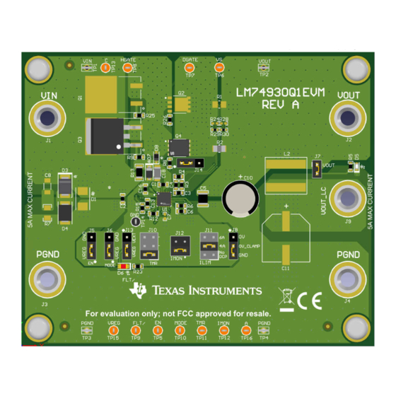
EVM User's Guide: LM74930Q1EVM LM74930-Q1
LM74930-Q1 Evaluation Module for Ideal Diode Controller
Description
The LM74930-Q1 Evaluation Module
(LM74930Q1EVM) helps designers evaluate the
operation and performance of the LM74930-Q1 ideal
diode controller with power path ON/OFF control,
overcurrent, short-circuit and overvoltage protection.
The wide input supply of LM74930-Q1, 4V to 65V,
allows protection and control of 12-V and 24-V
automotive battery powered ECUs. The LM74930-
Q1 can drive back-to-back external N-Channel
MOSFETs connected in common source topology
to realize surge stopper functionality. With first
MOSFET in the power path, the device allows load
disconnect (ON/OFF control) in case of overcurrent
and surge/overvoltage events using HGATE control.
An integrated ideal diode controller (DGATE) drives
the second MOSFET to replace a Schottky diode for
reverse input protection and output voltage holdup.
SLUUCW6 – NOVEMBER 2023
Submit Document Feedback
Features
•
Reverse current blocking feature required for
ORing application
•
Input reverse battery protection
•
Drives external back-to-back N-Channel MOSFETs
in common source configuration
•
Surge protection against transients like 200 V
unsuppressed load dump
•
Adjustable overcurrent and short circuit protection
•
Analog current monitor output with 10% accuracy
(IMON)
•
Adjustable overvoltage and undervoltage
•
MODE pin to allow bi-directional current flow
(MODE = Low)
Applications
•
12 V/24 V automotive reverse battery protection
•
Industrial transport
•
Redundant power supply ORing
LM74930Q1EVM
Copyright © 2023 Texas Instruments Incorporated
LM74930-Q1 Evaluation Module for Ideal Diode Controller
Description
1
Advertisement

Related Manuals for Texas Instruments LM74930Q1EVM


Summary of Contents for Texas Instruments LM74930Q1EVM
- Page 1 Description EVM User's Guide: LM74930Q1EVM LM74930-Q1 LM74930-Q1 Evaluation Module for Ideal Diode Controller Description Features The LM74930-Q1 Evaluation Module • Reverse current blocking feature required for (LM74930Q1EVM) helps designers evaluate the ORing application operation and performance of the LM74930-Q1 ideal •...
-
Page 2: Kit Contents
1 Evaluation Module Overview 1.1 Introduction This user’s guide describes the LM74930Q1EVM evaluation module for evaluating the performance of the LM74930-Q1 ideal diode controller devices. The LM74930-Q1 ideal diode controller drives and controls external back to back N-Channel MOSFETs to emulate an ideal diode rectifier with power path ON/OFF control, as well as overcurrent, short-circuit, and overvoltage protection. - Page 3 Hardware 2 Hardware 2.1 Test Points and Connectors Table 2-1 lists the LM74930Q1EVM evaluation board input and output connector functionality. Table 2-2 Table 2-3 describe the test point availability and the jumper functionality. Table 2-1. Input and Output Connector Functionality...
- Page 4 One resistive load or equivalent that can tolerate up to 50-A DC load at 60 V and capable of the output short. 2.3 Test Setup and Procedures Make sure the evaluation board has default jumper settings as shown in Table 2-4. Table 2-4. Default Jumper Setting for LM74930Q1EVM Evaluation Board Jumper Default Setting Functionality EN connected to VREG. EN pulled High.
- Page 5 6. Observe the shutdown profile of charge pump voltage (V – V ), output voltage, HGATE, and DGATE. Figure 2-2 shows an example of power-up with EN profile captured on the LM74930Q1EVM evaluation board. SLUUCW6 – NOVEMBER 2023 LM74930-Q1 Evaluation Module for Ideal Diode Controller Submit Document Feedback...
- Page 6 Figure 2-2. LM74930-Q1 Start-Up With VIN - HGATE, DGATE and VOUT Figure 2-3. LM74930-Q1 Start-Up With VIN - VS, CAP and HGATE LM74930-Q1 Evaluation Module for Ideal Diode Controller SLUUCW6 – NOVEMBER 2023 Submit Document Feedback Copyright © 2023 Texas Instruments Incorporated...
- Page 7 6. Observe OVCLAMP operation of LM74930-Q1 when input voltage is above OV threshold. Figure 2-4. Unsuppressed Load Dump 200 V - Output Clamp (OVCLAMP = GND) SLUUCW6 – NOVEMBER 2023 LM74930-Q1 Evaluation Module for Ideal Diode Controller Submit Document Feedback Copyright © 2023 Texas Instruments Incorporated...
- Page 8 2.3.3 Overcurrent Protection Test Use the following instructions to perform the overcurrent test on the LM74930Q1EVM. 1. Set the input supply voltage VIN to 12 V and current limit of 10 A. 2. Turn ON the power supply and observe start-up of output voltage, HGATE, and DGATE.
- Page 9 Hardware Figure 2-6. Auto-Retry Response of LM74930-Q1 for an Overcurrent Fault SLUUCW6 – NOVEMBER 2023 LM74930-Q1 Evaluation Module for Ideal Diode Controller Submit Document Feedback Copyright © 2023 Texas Instruments Incorporated...
- Page 10 3. Short the output to GND. That is, VOUT to GND with a cable and observe the short-circuit response of LM74930-Q1 using an oscilloscope. Figure 2-7 shows hot-short response of LM74930-Q1 on LM74930Q1EVM evaluation board. Figure 2-7. Output Hot-Short Response of LM74930-Q1 Device LM74930-Q1 Evaluation Module for Ideal Diode Controller SLUUCW6 –...
- Page 11 TP14 TP15 VREG MODE IMON 0.14ms 0.68ms NoOCP 2.6V at 4A 2.6V at 6A Figure 3-1. LM74930Q1EVM: Evaluation Module Schematic SLUUCW6 – NOVEMBER 2023 LM74930-Q1 Evaluation Module for Ideal Diode Controller Submit Document Feedback Copyright © 2023 Texas Instruments Incorporated...
-
Page 12: Pcb Layouts
3-4 through Figure 3-7 show PCB layout images. Figure 3-3. LM74930Q1EVM Board Bottom Overlay Figure 3-2. LM74930Q1EVM Board Top Overlay Figure 3-4. LM74930Q1EVM Board Top Layer Figure 3-5. LM74930Q1EVM Board Bottom Layer LM74930-Q1 Evaluation Module for Ideal Diode Controller SLUUCW6 –... - Page 13 Hardware Design Files Figure 3-6. LM74930Q1EVM Board Inner Layer 1 Figure 3-7. LM74930Q1EVM Board Inner Layer 2 SLUUCW6 – NOVEMBER 2023 LM74930-Q1 Evaluation Module for Ideal Diode Controller Submit Document Feedback Copyright © 2023 Texas Instruments Incorporated...
- Page 14 D8, D9 75 V SOD-323 1N4148WS-7-F Diodes Inc. SOD-323 4.7V Diode, Zener, 4.7 V, 300 mW, SOD-323 SOD-323 MM3Z4V7ST1G ON Semiconductor LM74930-Q1 Evaluation Module for Ideal Diode Controller SLUUCW6 – NOVEMBER 2023 Submit Document Feedback Copyright © 2023 Texas Instruments Incorporated...
- Page 15 RES, 24.0 k, 1%, 0.1 W, 0603 0603 RC0603FR-0724KL Yageo RES, 20.0 k, 1%, 0.125 W, AEC-Q200 20.0k 0805 ERJ-6ENF2002V Panasonic Grade 0, 0805 SLUUCW6 – NOVEMBER 2023 LM74930-Q1 Evaluation Module for Ideal Diode Controller Submit Document Feedback Copyright © 2023 Texas Instruments Incorporated...
- Page 16 RES, 200, 5%, 0.25 W, AEC-Q200 Grade 0, 1206 CRCW1206200RJNEA Vishay-Dale 1206 R24, R28 RES, 0, 5%, 0.063 W, 0402 0402 MCR01MZPJ000 Rohm LM74930-Q1 Evaluation Module for Ideal Diode Controller SLUUCW6 – NOVEMBER 2023 Submit Document Feedback Copyright © 2023 Texas Instruments Incorporated...
- Page 17 Additional Information 4 Additional Information Trademarks All trademarks are the property of their respective owners. SLUUCW6 – NOVEMBER 2023 LM74930-Q1 Evaluation Module for Ideal Diode Controller Submit Document Feedback Copyright © 2023 Texas Instruments Incorporated...
- Page 18 STANDARD TERMS FOR EVALUATION MODULES Delivery: TI delivers TI evaluation boards, kits, or modules, including any accompanying demonstration software, components, and/or documentation which may be provided together or separately (collectively, an “EVM” or “EVMs”) to the User (“User”) in accordance with the terms set forth herein.
- Page 19 www.ti.com Regulatory Notices: 3.1 United States 3.1.1 Notice applicable to EVMs not FCC-Approved: FCC NOTICE: This kit is designed to allow product developers to evaluate electronic components, circuitry, or software associated with the kit to determine whether to incorporate such items in a finished product and software developers to write software applications for use with the end product.
- Page 20 www.ti.com Concernant les EVMs avec antennes détachables Conformément à la réglementation d'Industrie Canada, le présent émetteur radio peut fonctionner avec une antenne d'un type et d'un gain maximal (ou inférieur) approuvé pour l'émetteur par Industrie Canada. Dans le but de réduire les risques de brouillage radioélectrique à...
- Page 21 www.ti.com EVM Use Restrictions and Warnings: 4.1 EVMS ARE NOT FOR USE IN FUNCTIONAL SAFETY AND/OR SAFETY CRITICAL EVALUATIONS, INCLUDING BUT NOT LIMITED TO EVALUATIONS OF LIFE SUPPORT APPLICATIONS. 4.2 User must read and apply the user guide and other available documentation provided by TI regarding the EVM prior to handling or using the EVM, including without limitation any warning or restriction notices.
- Page 22 Notwithstanding the foregoing, any judgment may be enforced in any United States or foreign court, and TI may seek injunctive relief in any United States or foreign court. Mailing Address: Texas Instruments, Post Office Box 655303, Dallas, Texas 75265 Copyright © 2023, Texas Instruments Incorporated...
-
Page 23: Important Notice
TI products. TI’s provision of these resources does not expand or otherwise alter TI’s applicable warranties or warranty disclaimers for TI products. TI objects to and rejects any additional or different terms you may have proposed. IMPORTANT NOTICE Mailing Address: Texas Instruments, Post Office Box 655303, Dallas, Texas 75265 Copyright © 2023, Texas Instruments Incorporated...
Need help?
Do you have a question about the LM74930Q1EVM and is the answer not in the manual?
Questions and answers