Advertisement
Quick Links
www.ti.com
User's Guide
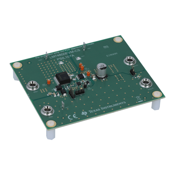
LM7480-Q1 Evaluation Module for Unsuppressed Load
Dump Protection: LM74800EVM-CS
This user's guide describes the LM74800EVM-CS Evaluation Module for evaluating the performance of Ideal
Diode Controller with Switched Output LM74800-Q1 and LM74801-Q1. The LM7480x-Q1 ideal diode controller
drives and controls external back to back N-Channel MOSFETs to emulate an ideal diode rectifier with power
path ON/OFF control and over voltage protection.
1
Introduction.............................................................................................................................................................................1
2 Description..............................................................................................................................................................................
3
Schematic................................................................................................................................................................................4
4 Test Equipment Requirements..............................................................................................................................................
5 Test Setup and Results..........................................................................................................................................................
History.......................................................................................................................................................................14
Trademarks
All trademarks are the property of their respective owners.
1 Introduction
TI's LM74800 Evaluation Module LM74800EVM-CS helps designers evaluate the operation and performance of
the LM74800-Q1 ideal diode controller with switched output.The LM7480x-Q1 ideal diode controller drives and
controls external back-to-back N-Channel MOSFETs to emulate an ideal diode rectifier with power path ON/OFF
control and overvoltage protection. This evaluation module demonstrates how LM74800-Q1 along with two back-
to-back N-Channel MOSFETs configured in common-source topology can provide 200-V unsuppressed load
dump protection with reverse battery protection to the downstream circuit. The first gate drive HGATE controls
an external N-channel MOSFET to turn off or clamp output voltage to acceptable safe level and the second gate
drive DGATE controls another external N-Channel MOSFET to emulate an ideal diode.
1.1 Features
Key features of the EVM include:
•
12-V and 24-V automotive reverse battery protection
•
Input operating range 3 V to 65 V
•
12-V battery protection 3 V to 40 V
•
24-V battery protection 3 V to 65 V
•
2-A Nominal, 2.5-A peak load current
•
Supports 200-V unsuppressed load dump protection
•
Enable ON/OFF control
•
Programmable over voltage cutoff and output clamp operation
•
Output voltage slew rate control
•
LED Indication for Output ON/OFF detection
•
On board TVS protection for automotive transient immunity
SLVUBU4 - MARCH 2021
Submit Document Feedback
ABSTRACT
Table of Contents
Materials........................................................................................................................................9
Copyright © 2021 Texas Instruments Incorporated
LM7480-Q1 Evaluation Module for Unsuppressed Load Dump Protection:
Table of Contents
2
5
5
1
LM74800EVM-CS
Advertisement

Related Manuals for Texas Instruments LM7480-Q1


Summary of Contents for Texas Instruments LM7480-Q1
-
Page 1: Table Of Contents
Output voltage slew rate control • LED Indication for Output ON/OFF detection • On board TVS protection for automotive transient immunity SLVUBU4 – MARCH 2021 LM7480-Q1 Evaluation Module for Unsuppressed Load Dump Protection: Submit Document Feedback LM74800EVM-CS Copyright © 2021 Texas Instruments Incorporated... -
Page 2: Description
Q1. Test Point labelled VIN (TP1) measures input voltage, VOUT (TP2) measure output voltage. Test Point labelled VA (TP6) measures the source voltage of Q1 and Q2 MOSFETs which is also connected to the A LM7480-Q1 Evaluation Module for Unsuppressed Load Dump Protection: SLVUBU4 – MARCH 2021... - Page 3 1-2 OVP set to Output Clamp (hysteretic) at 37.5 V • 2-3 OVP set to Input OVP Cutoff at 38.4 V Enables LED indication for output SLVUBU4 – MARCH 2021 LM7480-Q1 Evaluation Module for Unsuppressed Load Dump Protection: Submit Document Feedback LM74800EVM-CS Copyright © 2021 Texas Instruments Incorporated...
-
Page 4: Schematic
GND3 Green GND4 3.48k TP10 GND2 0.015uF EN/UVLO PLM74800DRRRQ1 AGND SGND AGND AGND SGND Figure 3-1. LM74800EVM-CS Schematic LM7480-Q1 Evaluation Module for Unsuppressed Load Dump Protection: LM74800EVM-CS SLVUBU4 – MARCH 2021 Submit Document Feedback Copyright © 2021 Texas Instruments Incorporated... -
Page 5: Test Equipment Requirements
Table 5-1. Default Jumper Setting for LM74800EVM-CS 1-2 or connect 2 to external 2-3, OVP to Input 1-2, Output LED Indication enable control SLVUBU4 – MARCH 2021 LM7480-Q1 Evaluation Module for Unsuppressed Load Dump Protection: Submit Document Feedback LM74800EVM-CS Copyright © 2021 Texas Instruments Incorporated... - Page 6 Set the load to 200 mA, trigger to Channel 1 rising and turn ON the power supply. Start-up behavior of LM74800EVM-CS is captured in Figure 5-2. LM7480-Q1 Evaluation Module for Unsuppressed Load Dump Protection: SLVUBU4 – MARCH 2021 LM74800EVM-CS Submit Document Feedback...
- Page 7 Figure 5-6. Unsuppressed Load Dump 200 V - Figure 5-7. Unsuppressed Load Dump 200 V - Output Clamp Output Cut-off SLVUBU4 – MARCH 2021 LM7480-Q1 Evaluation Module for Unsuppressed Load Dump Protection: Submit Document Feedback LM74800EVM-CS Copyright © 2021 Texas Instruments Incorporated...
- Page 8 Test Setup and Results www.ti.com 5.4 ISO 7637-2 Pulse 1 –600 V 50 Ω Figure 5-8. ISO 7637-2 Pulse 1 –600 V 50 Ω LM7480-Q1 Evaluation Module for Unsuppressed Load Dump Protection: SLVUBU4 – MARCH 2021 LM74800EVM-CS Submit Document Feedback...
-
Page 9: Board Layout And Bill Of Materials
6.1 Board Layout Figure 6-1. Component Placement TOP Figure 6-2. Component Placement BOTTOM Figure 6-3. TOP Layer Routing SLVUBU4 – MARCH 2021 LM7480-Q1 Evaluation Module for Unsuppressed Load Dump Protection: Submit Document Feedback LM74800EVM-CS Copyright © 2021 Texas Instruments Incorporated... - Page 10 Board Layout and Bill of Materials www.ti.com Figure 6-4. BOTTOM Layer Routing LM7480-Q1 Evaluation Module for Unsuppressed Load Dump Protection: SLVUBU4 – MARCH 2021 LM74800EVM-CS Submit Document Feedback Copyright © 2021 Texas Instruments Incorporated...
- Page 11 LED, Green, SMD 1.6x0.8x0.8mm LTST-C190GKT Lite-On Diode, Switching, 75 75 V V, 0.15 A, AEC-Q101, SOD-323 1N4148WS-7-F Diodes Inc. SOD-323 SLVUBU4 – MARCH 2021 LM7480-Q1 Evaluation Module for Unsuppressed Load Dump Protection: LM74800EVM-CS Submit Document Feedback Copyright © 2021 Texas Instruments Incorporated...
- Page 12 AEC-Q200 Grade 0, 0603 Vishay-Dale 0603 RES, 0, 5%, 0.1 W, CRCW06030000Z0E AEC-Q200 Grade 0, 0603 Vishay-Dale 0603 LM7480-Q1 Evaluation Module for Unsuppressed Load Dump Protection: LM74800EVM-CS SLVUBU4 – MARCH 2021 Submit Document Feedback Copyright © 2021 Texas Instruments Incorporated...
- Page 13 DPAK AUIRFR4615TRL International Rectifier None DPAK RES, 10 k, 5%, 0.5 W, 10 k 1210 RC1210JR-0710KL Yageo 1210 SLVUBU4 – MARCH 2021 LM7480-Q1 Evaluation Module for Unsuppressed Load Dump Protection: LM74800EVM-CS Submit Document Feedback Copyright © 2021 Texas Instruments Incorporated...
-
Page 14: Revision History
NOTE: Page numbers for previous revisions may differ from page numbers in the current version. DATE REVISION NOTES March 2021 Initial release LM7480-Q1 Evaluation Module for Unsuppressed Load Dump Protection: SLVUBU4 – MARCH 2021 LM74800EVM-CS Submit Document Feedback Copyright © 2021 Texas Instruments Incorporated... - Page 15 STANDARD TERMS FOR EVALUATION MODULES Delivery: TI delivers TI evaluation boards, kits, or modules, including any accompanying demonstration software, components, and/or documentation which may be provided together or separately (collectively, an “EVM” or “EVMs”) to the User (“User”) in accordance with the terms set forth herein.
- Page 16 www.ti.com Regulatory Notices: 3.1 United States 3.1.1 Notice applicable to EVMs not FCC-Approved: FCC NOTICE: This kit is designed to allow product developers to evaluate electronic components, circuitry, or software associated with the kit to determine whether to incorporate such items in a finished product and software developers to write software applications for use with the end product.
- Page 17 www.ti.com Concernant les EVMs avec antennes détachables Conformément à la réglementation d'Industrie Canada, le présent émetteur radio peut fonctionner avec une antenne d'un type et d'un gain maximal (ou inférieur) approuvé pour l'émetteur par Industrie Canada. Dans le but de réduire les risques de brouillage radioélectrique à...
- Page 18 www.ti.com EVM Use Restrictions and Warnings: 4.1 EVMS ARE NOT FOR USE IN FUNCTIONAL SAFETY AND/OR SAFETY CRITICAL EVALUATIONS, INCLUDING BUT NOT LIMITED TO EVALUATIONS OF LIFE SUPPORT APPLICATIONS. 4.2 User must read and apply the user guide and other available documentation provided by TI regarding the EVM prior to handling or using the EVM, including without limitation any warning or restriction notices.
- Page 19 Notwithstanding the foregoing, any judgment may be enforced in any United States or foreign court, and TI may seek injunctive relief in any United States or foreign court. Mailing Address: Texas Instruments, Post Office Box 655303, Dallas, Texas 75265 Copyright © 2019, Texas Instruments Incorporated...
- Page 20 TI products. TI’s provision of these resources does not expand or otherwise alter TI’s applicable warranties or warranty disclaimers for TI products.IMPORTANT NOTICE Mailing Address: Texas Instruments, Post Office Box 655303, Dallas, Texas 75265 Copyright © 2021, Texas Instruments Incorporated...
Need help?
Do you have a question about the LM7480-Q1 and is the answer not in the manual?
Questions and answers