Table of Contents
Advertisement
Quick Links
www.ti.com
EVM User's Guide: LM706A0QEVM
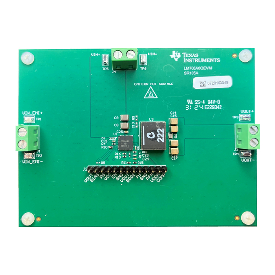
LM706A0-Q1 Buck Converter Evaluation Module
Description
The LM706A0QEVM high-density EVM is designed to
use a regulated or non-regulated high-voltage input
rail ranging from 8V to 65V to produce a tightly
regulated output voltage of 3.3V at load currents
up to 10A. This wide V
IN
offers outsized voltage rating and operating margin to
withstand supply rail voltage transients.
The free-running switching frequency is 400kHz and
is synchronizable to an external clock signal at a
higher or lower frequency. The power-train passive
components selected for this EVM, including buck
inductors and ceramic input and output capacitors,
are automotive AEC-Q200 rated and are available
from multiple component vendors.
Features
•
Wide input voltage operating range of 8V to 65V
•
1% accurate fixed 3.3V, 5V, or adjustable output
down to 0.8V
•
Switching frequency of 400kHz externally
synchronizable up or down by 20%
•
Full-load efficiency of 89.3% at 12V
24V
and 85.4% at 48V
IN
•
260µA operating current at 48V
•
Designed for low Electromagnetic Interference
(EMI)
SNVU917 – SEPTEMBER 2024
Submit Document Feedback
range DC/DC device
, 88.1% at
IN
IN
IN
Copyright © 2024 Texas Instruments Incorporated
– Dual-random spread spectrum EMI mitigation
– Meets CISPR 25 Class 5 and UNECE Reg 10
EMI standards
•
Peak current-mode control architecture provides
fast line and load transient response
– Integrated slope compensation adaptive with
switching frequency
– Forced pulsed width modulation (FPWM) or
pulsed frequency modulation (PFM) operation
– Optional internal or external loop compensation
•
Integrated high-side and low-side power MOSFETs
•
Overcurrent protection (OCP) with hiccup mode for
sustained overload conditions
•
SYNCOUT signal 180° out-of-phase with internal
clock
•
Power-Good signal with 100kΩ pullup resistor to
VCC
•
Internal 3ms soft start
•
Fully assembled, tested, and proven PCB layout
Applications
•
High-current
automotive electronic systems
•
ADAS
and
body
electronics
•
Infotainment systems
•
Automotive HEV/EV powertrain systems
LM706A0-Q1 Buck Converter Evaluation Module
Description
and
instrument clusters
1
Advertisement
Table of Contents

Subscribe to Our Youtube Channel
Related Manuals for Texas Instruments LM706A0-Q1


Summary of Contents for Texas Instruments LM706A0-Q1
- Page 1 Description EVM User's Guide: LM706A0QEVM LM706A0-Q1 Buck Converter Evaluation Module – Dual-random spread spectrum EMI mitigation Description – Meets CISPR 25 Class 5 and UNECE Reg 10 The LM706A0QEVM high-density EVM is designed to EMI standards use a regulated or non-regulated high-voltage input •...
-
Page 2: Kit Contents
1.2 Kit Contents • LM706A0QEVM Circuit Board • EVM Disclaimer Read Me • Prototype EVM Disclaimer Read Me 1.3 Specification The following figure shows the schematic of an LM706A0-Q1-based synchronous buck converter. 1µH = 4.5V...65V 20.5k 100k © ¨ ¥... -
Page 3: Test Setup And Procedure
Electronic Load Voltmeter 1 Voltmeter 2 Figure 2-1. EVM Test Setup Note Refer to the LM706A0-Q1 65V, 10A, Automotive, High-Efficiency Buck Converter Optimized for High Power Density data sheet, LM706A0-Q1 Quickstart Calculator, and WEBENCH® Power Designer additional guidance pertaining to component selection and converter operation. - Page 4 6. Set the load current to 5A (50% rated load) and vary the input source voltage from 8V to 65V; V must remain within the line regulation specification. 7. Decrease load to 0A. Decrease input source voltage to 0V. LM706A0-Q1 Buck Converter Evaluation Module SNVU917 – SEPTEMBER 2024 Submit Document Feedback Copyright © 2024 Texas Instruments Incorporated...
- Page 5 The recommended airflow when operating at input voltages greater than 60V is 100 LFM. SNVU917 – SEPTEMBER 2024 LM706A0-Q1 Buck Converter Evaluation Module Submit Document Feedback Copyright © 2024 Texas Instruments Incorporated...
- Page 6 VIN = 60V 0.001 0.01 Output Current (A) Figure 3-2. Efficiency, V = 5V to 60V, V = 3.3V, PFM Mode, Logarithmic Scale LM706A0-Q1 Buck Converter Evaluation Module SNVU917 – SEPTEMBER 2024 Submit Document Feedback Copyright © 2024 Texas Instruments Incorporated...
- Page 7 = 5V to 60V, V = 3.3V, FPWM Mode, Linear Scale Figure 3-4. Efficiency, V = 5V to 60V, V = 3.3V, FPWM Mode, Logarithmic Scale SNVU917 – SEPTEMBER 2024 LM706A0-Q1 Buck Converter Evaluation Module Submit Document Feedback Copyright © 2024 Texas Instruments Incorporated...
- Page 8 SW 10V / DIV 20ms / DIV Figure 3-6. Steady State Operation in PFM Mode, V = 24V, V = 3.3V, I = 0A LM706A0-Q1 Buck Converter Evaluation Module SNVU917 – SEPTEMBER 2024 Submit Document Feedback Copyright © 2024 Texas Instruments Incorporated...
- Page 9 2V / DIV 10ms / DIV Figure 3-8. Short-Circuit Recovery V = 24V, V = 3.3V, I = 10A, F = 400kHz, FPWM SNVU917 – SEPTEMBER 2024 LM706A0-Q1 Buck Converter Evaluation Module Submit Document Feedback Copyright © 2024 Texas Instruments Incorporated...
- Page 10 PG 5V / DIV 2ms / DIV Figure 3-10. Start-Up, V = 24V, V = 3.3V, I = 10A Resistive Load, F = 400kHzm FPWM LM706A0-Q1 Buck Converter Evaluation Module SNVU917 – SEPTEMBER 2024 Submit Document Feedback Copyright © 2024 Texas Instruments Incorporated...
-
Page 11: Frequency (Hz)
= crossover frequency, PM = phase margin. Figure 3-11. Bode Plot, V = 24V, V = 3.3V, I = 10A Resistive Load SNVU917 – SEPTEMBER 2024 LM706A0-Q1 Buck Converter Evaluation Module Submit Document Feedback Copyright © 2024 Texas Instruments Incorporated... - Page 12 Figure 3-12 Figure 3-13 presents the EMI performance of the LM706A0-Q1 EVM at 13.5V and 24V input with DRSS EMI mitigation disabled. Conducted emissions are measured over a frequency range of 150kHz to 108MHz using a 5µH LISN according to the CISPR 25 specification. CISPR 25 Class 5 peak and average limit lines are denoted in red.
- Page 13 = 25°C, No Airflow Figure 3-15. Thermal Performance, V = 24V, V = 3.3V, I = 10A, T = 25°C, No Airflow SNVU917 – SEPTEMBER 2024 LM706A0-Q1 Buck Converter Evaluation Module Submit Document Feedback Copyright © 2024 Texas Instruments Incorporated...
- Page 14 Hardware Design Files www.ti.com 4 Hardware Design Files 4.1 Schematic The following image shows the EVM schematic. Figure 4-1. EVM Schematic LM706A0-Q1 Buck Converter Evaluation Module SNVU917 – SEPTEMBER 2024 Submit Document Feedback Copyright © 2024 Texas Instruments Incorporated...
- Page 15 4.2 PCB Layout Figure 4-2 through Figure 4-9 show the design of the LM706A0-Q1 EVM using a six-layer PCB with 2oz copper thickness. Figure 4-2. Top Copper (Top View) Figure 4-3. Layer 2 Copper (Top View) SNVU917 – SEPTEMBER 2024...
- Page 16 Hardware Design Files www.ti.com Figure 4-4. Layer 3 Copper (Top View) Figure 4-5. Layer 4 Copper (Top View) LM706A0-Q1 Buck Converter Evaluation Module SNVU917 – SEPTEMBER 2024 Submit Document Feedback Copyright © 2024 Texas Instruments Incorporated...
- Page 17 Hardware Design Files Figure 4-6. Layer 5 Copper (Top View) Figure 4-7. Bottom Copper (Top View) SNVU917 – SEPTEMBER 2024 LM706A0-Q1 Buck Converter Evaluation Module Submit Document Feedback Copyright © 2024 Texas Instruments Incorporated...
- Page 18 Hardware Design Files www.ti.com 4.2.1 Component Drawings Figure 4-8. Top Component Drawing Figure 4-9. Bottom Component Drawing LM706A0-Q1 Buck Converter Evaluation Module SNVU917 – SEPTEMBER 2024 Submit Document Feedback Copyright © 2024 Texas Instruments Incorporated...
- Page 19 Hardware Design Files 4.2.2 Multi-Layer Stackup Figure 4-10. Layer Stackup SNVU917 – SEPTEMBER 2024 LM706A0-Q1 Buck Converter Evaluation Module Submit Document Feedback Copyright © 2024 Texas Instruments Incorporated...
-
Page 20: Bill Of Materials
Keystone H7, H8, H9, H10 #4-40 Pan Head Machine Screw Phillips Drive Nylon NY PMS 440 0038 PH Building Fasteners IC, LM706A0-Q1, 65V, 10A Synchronous DC/DC Buck Converter with LM706A0QRRXRQ1 Ultra-Low IQ, VQFN-29 PCB1 PCB, FR4, 6 layer, 2 oz –... -
Page 21: Compliance Information
6 Related Documentation For related documentation, see the following: • Texas Instruments, LM706A0-Q1 65V, 10A, Automotive, High-Efficiency Buck Converter Optimized for High Power Density data sheet • Texas Instruments, Reduce Buck Converter EMI and Voltage Stress by Minimizing Inductive Parasitics analog applications journal •... - Page 22 STANDARD TERMS FOR EVALUATION MODULES Delivery: TI delivers TI evaluation boards, kits, or modules, including any accompanying demonstration software, components, and/or documentation which may be provided together or separately (collectively, an “EVM” or “EVMs”) to the User (“User”) in accordance with the terms set forth herein.
- Page 23 www.ti.com Regulatory Notices: 3.1 United States 3.1.1 Notice applicable to EVMs not FCC-Approved: FCC NOTICE: This kit is designed to allow product developers to evaluate electronic components, circuitry, or software associated with the kit to determine whether to incorporate such items in a finished product and software developers to write software applications for use with the end product.
- Page 24 www.ti.com Concernant les EVMs avec antennes détachables Conformément à la réglementation d'Industrie Canada, le présent émetteur radio peut fonctionner avec une antenne d'un type et d'un gain maximal (ou inférieur) approuvé pour l'émetteur par Industrie Canada. Dans le but de réduire les risques de brouillage radioélectrique à...
- Page 25 www.ti.com EVM Use Restrictions and Warnings: 4.1 EVMS ARE NOT FOR USE IN FUNCTIONAL SAFETY AND/OR SAFETY CRITICAL EVALUATIONS, INCLUDING BUT NOT LIMITED TO EVALUATIONS OF LIFE SUPPORT APPLICATIONS. 4.2 User must read and apply the user guide and other available documentation provided by TI regarding the EVM prior to handling or using the EVM, including without limitation any warning or restriction notices.
- Page 26 Notwithstanding the foregoing, any judgment may be enforced in any United States or foreign court, and TI may seek injunctive relief in any United States or foreign court. Mailing Address: Texas Instruments, Post Office Box 655303, Dallas, Texas 75265 Copyright © 2023, Texas Instruments Incorporated...
- Page 27 TI products. TI’s provision of these resources does not expand or otherwise alter TI’s applicable warranties or warranty disclaimers for TI products. TI objects to and rejects any additional or different terms you may have proposed. IMPORTANT NOTICE Mailing Address: Texas Instruments, Post Office Box 655303, Dallas, Texas 75265 Copyright © 2024, Texas Instruments Incorporated...
Need help?
Do you have a question about the LM706A0-Q1 and is the answer not in the manual?
Questions and answers