Table of Contents
Advertisement
Quick Links
This user's guide describes the evaluation module (EVM) for TI's ideal diode controller, LM74700-Q1. This
document provides configuration information and test setup details for evaluating LM74700-Q1 devices.
An EVM schematic, board layout images, and bill of materials (BOM) are included.
...................................................................................................................
1
..........................................................................................................................
2
2.1
2.2
2.3
.....................................................................................................................
3
3.1
3.2
4
4.1
4.2
1
2
3
4
Reverse Polarity 12 V to -12 V
5
6
7
8
9
10
11
1
Bill of Materials
Trademarks
All trademarks are the property of their respective owners.
SNOU153A - October 2017 - Revised February 2019
Submit Documentation Feedback
.........................................................................................
.........................................................................................................
............................................................................................................
.......................................................................................
..................................................................................................
.......................................................................................................
....................................................................................................
................................................................................
................................................................................................................
..................................................................................................
...........................................................................................
..........................................................................................
.......................................................................................
...................................................................................
.........................................................................................
....................................................................................
.............................................................................................................
Copyright © 2017-2019, Texas Instruments Incorporated
SNOU153A - October 2017 - Revised February 2019
LM74700 Evaluation Module
Contents
...............................................................
List of Figures
.........................................................................
...........................................................................
List of Tables
User's Guide
LM74700 Evaluation Module
2
2
2
3
4
5
5
6
7
7
11
2
3
4
5
5
6
6
7
8
9
10
11
1
Advertisement
Table of Contents

Related Manuals for Texas Instruments LM74700EVM


Summary of Contents for Texas Instruments LM74700EVM
-
Page 1: Table Of Contents
LM74700EVM Bottom Layer Routing List of Tables ......................Bill of Materials Trademarks All trademarks are the property of their respective owners. SNOU153A – October 2017 – Revised February 2019 LM74700 Evaluation Module Submit Documentation Feedback Copyright © 2017–2019, Texas Instruments Incorporated... -
Page 2: Introduction
Setup This section describes the jumpers and connectors on the EVM, and how to properly connect, setup, and use the LM74700EVM. Ensure the power supply is turned off while making connections on the board. I/O Connector Description • VIN J1: Power input connector to the positive rail of the input power supply •... -
Page 3: Board Setup
Board Setup Before applying power to the LM74700EVM, verify all external connections. Turn off external power supplies and connect them with the proper polarity to the VIN and GND1 connectors. An electronic or resistive load must be connected at the output VOUT and GND2 connectors. The tests outlined in this document are conducted with 3-A constant current as the load and 12 V at the input. -
Page 4: Schematic
33 V 220 µF 58 V 0.33 µF LM74700QDBVRQ1 24 V GND2 GND1 1 µF SGND SGND Figure 3. LM74700EVM Schematic LM74700 Evaluation Module SNOU153A – October 2017 – Revised February 2019 Submit Documentation Feedback Copyright © 2017–2019, Texas Instruments Incorporated... -
Page 5: Operation
Operation Reverse Polarity Protection A dynamic voltage pulse from 12 V to –12 V is applied at the input of the LM74700EVM. Figure 4 shows the input voltage (CH1) drops down to –12 V and the output voltage (CH2) does not go negative. -
Page 6: Oring Application
Next, the 12-V source at EVM2 is turned off for a period of time and turned on again, the output (CH2) does not change. Figure 7 captures this test. Figure 7. ORing Application 12-V – Lower Supply Test LM74700 Evaluation Module SNOU153A – October 2017 – Revised February 2019 Submit Documentation Feedback Copyright © 2017–2019, Texas Instruments Incorporated... -
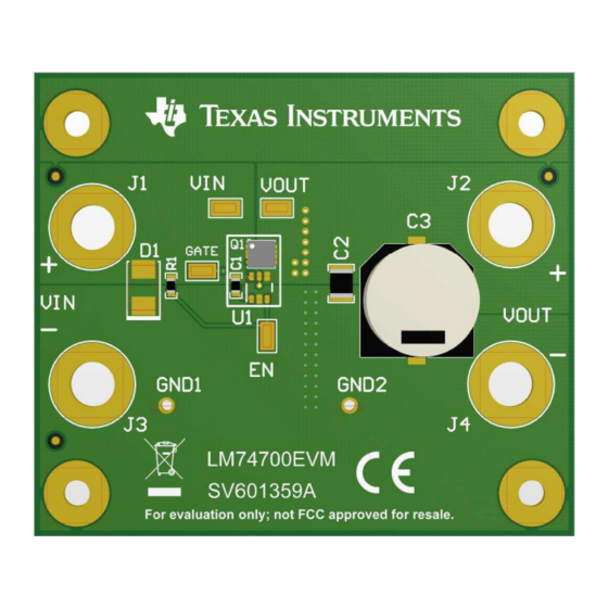
Page 7: Evm Board Assembly Drawings And Layout Guidelines
PCB Drawings Figure 8 through Figure 11 show component placement and layout of this EVM. Figure 8. LM74700EVM Top Side Placement SNOU153A – October 2017 – Revised February 2019 LM74700 Evaluation Module Submit Documentation Feedback Copyright © 2017–2019, Texas Instruments Incorporated... -
Page 8: Lm74700Evm Bottom Side Placement
EVM Board Assembly Drawings and Layout Guidelines www.ti.com Figure 9. LM74700EVM Bottom Side Placement LM74700 Evaluation Module SNOU153A – October 2017 – Revised February 2019 Submit Documentation Feedback Copyright © 2017–2019, Texas Instruments Incorporated... -
Page 9: Lm74700Evm Top Layer Routing
EVM Board Assembly Drawings and Layout Guidelines www.ti.com Figure 10. LM74700EVM Top Layer Routing SNOU153A – October 2017 – Revised February 2019 LM74700 Evaluation Module Submit Documentation Feedback Copyright © 2017–2019, Texas Instruments Incorporated... -
Page 10: Lm74700Evm Bottom Layer Routing
EVM Board Assembly Drawings and Layout Guidelines www.ti.com Figure 11. LM74700EVM Bottom Layer Routing LM74700 Evaluation Module SNOU153A – October 2017 – Revised February 2019 Submit Documentation Feedback Copyright © 2017–2019, Texas Instruments Incorporated... -
Page 11: Bill Of Materials
FID3, FID4, FID5, FID6 Not Fitted MOSFET, N-CH, 60 V, 17.9 A, AEC- DMT6005LPS-13 Diodes Inc. 8-PowerTDFN 60 V Q101, 8-PowerTDFN SNOU153A – October 2017 – Revised February 2019 LM74700 Evaluation Module Submit Documentation Feedback Copyright © 2017–2019, Texas Instruments Incorporated... - Page 12 Changed connectors from VINA to VIN ..................• Changed connectors from VOUTA to VOUT .......................... • Updated Figure 3 ......................• Updated Bill of Materials table Revision History SNOU153A – October 2017 – Revised February 2019 Submit Documentation Feedback Copyright © 2017–2019, Texas Instruments Incorporated...
- Page 13 STANDARD TERMS FOR EVALUATION MODULES Delivery: TI delivers TI evaluation boards, kits, or modules, including any accompanying demonstration software, components, and/or documentation which may be provided together or separately (collectively, an “EVM” or “EVMs”) to the User (“User”) in accordance with the terms set forth herein.
- Page 14 www.ti.com Regulatory Notices: 3.1 United States 3.1.1 Notice applicable to EVMs not FCC-Approved: FCC NOTICE: This kit is designed to allow product developers to evaluate electronic components, circuitry, or software associated with the kit to determine whether to incorporate such items in a finished product and software developers to write software applications for use with the end product.
- Page 15 www.ti.com Concernant les EVMs avec antennes détachables Conformément à la réglementation d'Industrie Canada, le présent émetteur radio peut fonctionner avec une antenne d'un type et d'un gain maximal (ou inférieur) approuvé pour l'émetteur par Industrie Canada. Dans le but de réduire les risques de brouillage radioélectrique à...
- Page 16 www.ti.com EVM Use Restrictions and Warnings: 4.1 EVMS ARE NOT FOR USE IN FUNCTIONAL SAFETY AND/OR SAFETY CRITICAL EVALUATIONS, INCLUDING BUT NOT LIMITED TO EVALUATIONS OF LIFE SUPPORT APPLICATIONS. 4.2 User must read and apply the user guide and other available documentation provided by TI regarding the EVM prior to handling or using the EVM, including without limitation any warning or restriction notices.
- Page 17 Notwithstanding the foregoing, any judgment may be enforced in any United States or foreign court, and TI may seek injunctive relief in any United States or foreign court. Mailing Address: Texas Instruments, Post Office Box 655303, Dallas, Texas 75265 Copyright © 2019, Texas Instruments Incorporated...
- Page 18 TI products. TI’s provision of these resources does not expand or otherwise alter TI’s applicable warranties or warranty disclaimers for TI products. Mailing Address: Texas Instruments, Post Office Box 655303, Dallas, Texas 75265 Copyright © 2019, Texas Instruments Incorporated...
Need help?
Do you have a question about the LM74700EVM and is the answer not in the manual?
Questions and answers