Table of Contents
Advertisement
Quick Links
www.ti.com
EVM User's Guide: LM74704Q1EVM LM74704-Q1 LM74703-Q1
Evaluation Module for LM74704-Q1 and LM74703-Q1 Ideal
Diode Controllers
Description
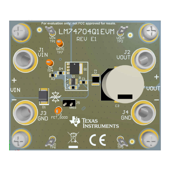
The LM74704Q1EVM assists designers to evaluate
the operation and performance of the LM74704-Q1
and LM74703-Q1 ideal diode controllers (8-pin DDF
package). This evaluation module demonstrates how
an N-channel power MOSFET driven by LM74704-Q1
can emulate a very-low forward voltage diode with low
I
and low-leakage current flowing through the IC.
Q
Features
•
Reverse current blocking feature required for
ORing application
•
Input reverse battery protection
SNOU196 – MAY 2023
Submit Document Feedback
•
FET_GOOD output to indicate external MOSFET
health status
•
On-board voltage regulator to provide pull-up
voltage for open-drain FET_GOOD variant,
LM74704-Q1
•
Meets 12-V battery automotive ISO7637 and
ISO16750-2 transient requirements
Applications
•
Automotive ADAS systems - camera
•
Automotive infotainment systems - digital cluster,
head unit
•
Body electronics and lighting
LM74704Q1EVM
Evaluation Module for LM74704-Q1 and LM74703-Q1 Ideal Diode Controllers
Copyright © 2023 Texas Instruments Incorporated
Description
1
Advertisement
Table of Contents

Related Manuals for Texas Instruments LM74704Q1EVM


Summary of Contents for Texas Instruments LM74704Q1EVM
- Page 1 Description EVM User's Guide: LM74704Q1EVM LM74704-Q1 LM74703-Q1 Evaluation Module for LM74704-Q1 and LM74703-Q1 Ideal Diode Controllers • FET_GOOD output to indicate external MOSFET Description health status The LM74704Q1EVM assists designers to evaluate • On-board voltage regulator to provide pull-up...
-
Page 2: Kit Contents
1 Evaluation Module Overview This user’s guide describes the LM74704Q1EVM evaluation modules (EVM). The default mounted device is LM74704-Q1, and the EVM is also for LM74703-Q1 device as well. This guide provides configuration information, test setup details and contains the EVM schematics, bill of materials, assembly drawings, and top and bottom board layouts. - Page 3 This section describes the jumpers and connectors on the EVM, and how to properly connect, setup, and use the LM74704Q1EVM. Verify the power supply is turned off while making connections on the board. 2.1.1 I/O Connectors, Jumper and Test Points Description...
-
Page 4: Board Setup
2.1.2 Board Setup Before applying power to the LM74704Q1EVM, verify all external connections. Turn off external power supplies and connect them with the proper polarity to the VIN and GND connectors. An electronic or resistive load must be connected at the output VOUT and GND connectors. The tests outlined in this document are conducted with 3-A constant current as the load and 12 V at the input. - Page 5 FET_GOOD and does not require an external pull-up voltage. 5. Turn ON the power supply. 6. Observe the start-up profile of VIN, VOUT, GATE and FET_GOOD. SNOU196 – MAY 2023 Evaluation Module for LM74704-Q1 and LM74703-Q1 Ideal Diode Controllers Submit Document Feedback Copyright © 2023 Texas Instruments Incorporated...
- Page 6 Figure 2-5. FETGOOD During Startup with FET Short (LM74703-Q1) 3 Hardware Design Files Users can request the design files at https://www.ti.com. Evaluation Module for LM74704-Q1 and LM74703-Q1 Ideal Diode Controllers SNOU196 – MAY 2023 Submit Document Feedback Copyright © 2023 Texas Instruments Incorporated...
- Page 7 VCAP- CATHODE 100nF VCAP+ FETGOOD LM74704DDF 575-8 575-8 CATHODE VREG 10.0k 2.2µF MM3Z4V7ST1G 4.7V Figure 3-1. LM74704Q1EVM Schematic SNOU196 – MAY 2023 Evaluation Module for LM74704-Q1 and LM74703-Q1 Ideal Diode Controllers Submit Document Feedback Copyright © 2023 Texas Instruments Incorporated...
-
Page 8: Pcb Drawings
Figure 3-2 through Figure 3-5 show component placement and layout of this EVM. Figure 3-2. LM74704Q1EVM Top Side Placement Figure 3-3. LM74704Q1EVM Bottom Side Placement Evaluation Module for LM74704-Q1 and LM74703-Q1 Ideal Diode Controllers SNOU196 – MAY 2023 Submit Document Feedback... - Page 9 Hardware Design Files Figure 3-4. LM74704Q1EVM Top Layer Routing Figure 3-5. LM74704Q1EVM Bottom Layer Routing SNOU196 – MAY 2023 Evaluation Module for LM74704-Q1 and LM74703-Q1 Ideal Diode Controllers Submit Document Feedback Copyright © 2023 Texas Instruments Incorporated...
-
Page 10: Bill Of Materials
SMBJ58A-13-F Diodes Inc. Vc, SMB Diode, TVS, Uni, 24 V, 38.9 24 V SMBJ24A-13-F Diodes Inc. Vc, SMB Evaluation Module for LM74704-Q1 and LM74703-Q1 Ideal Diode Controllers SNOU196 – MAY 2023 Submit Document Feedback Copyright © 2023 Texas Instruments Incorporated... - Page 11 60 V SOT669 PSMN5R6-60YL Nexperia SOT669 4 Additional Information Trademarks All trademarks are the property of their respective owners. SNOU196 – MAY 2023 Evaluation Module for LM74704-Q1 and LM74703-Q1 Ideal Diode Controllers Submit Document Feedback Copyright © 2023 Texas Instruments Incorporated...
- Page 12 STANDARD TERMS FOR EVALUATION MODULES Delivery: TI delivers TI evaluation boards, kits, or modules, including any accompanying demonstration software, components, and/or documentation which may be provided together or separately (collectively, an “EVM” or “EVMs”) to the User (“User”) in accordance with the terms set forth herein.
- Page 13 www.ti.com Regulatory Notices: 3.1 United States 3.1.1 Notice applicable to EVMs not FCC-Approved: FCC NOTICE: This kit is designed to allow product developers to evaluate electronic components, circuitry, or software associated with the kit to determine whether to incorporate such items in a finished product and software developers to write software applications for use with the end product.
- Page 14 www.ti.com Concernant les EVMs avec antennes détachables Conformément à la réglementation d'Industrie Canada, le présent émetteur radio peut fonctionner avec une antenne d'un type et d'un gain maximal (ou inférieur) approuvé pour l'émetteur par Industrie Canada. Dans le but de réduire les risques de brouillage radioélectrique à...
- Page 15 www.ti.com EVM Use Restrictions and Warnings: 4.1 EVMS ARE NOT FOR USE IN FUNCTIONAL SAFETY AND/OR SAFETY CRITICAL EVALUATIONS, INCLUDING BUT NOT LIMITED TO EVALUATIONS OF LIFE SUPPORT APPLICATIONS. 4.2 User must read and apply the user guide and other available documentation provided by TI regarding the EVM prior to handling or using the EVM, including without limitation any warning or restriction notices.
- Page 16 Notwithstanding the foregoing, any judgment may be enforced in any United States or foreign court, and TI may seek injunctive relief in any United States or foreign court. Mailing Address: Texas Instruments, Post Office Box 655303, Dallas, Texas 75265 Copyright © 2023, Texas Instruments Incorporated...
-
Page 17: Important Notice
TI products. TI’s provision of these resources does not expand or otherwise alter TI’s applicable warranties or warranty disclaimers for TI products. TI objects to and rejects any additional or different terms you may have proposed. IMPORTANT NOTICE Mailing Address: Texas Instruments, Post Office Box 655303, Dallas, Texas 75265 Copyright © 2023, Texas Instruments Incorporated...
Need help?
Do you have a question about the LM74704Q1EVM and is the answer not in the manual?
Questions and answers