
Related Manuals for SMC Networks PSE303-LBC


Summary of Contents for SMC Networks PSE303-LBC
- Page 1 No.PS※※-OMG0002-G PRODUCT NAME Pressure Sensor Controller MODEL / Series / Product Number PSE300...
-
Page 2: Table Of Contents
Table of Contents Safety Instructions Model Indication and How to Order Summary of Product parts Mounting and Installation Installation Wiring Internal circuit and wiring example Setting Pressure Setting Other Functions Maintenance Troubleshooting Specification Specifications Dimensions No.PS※※-OMG0002-G... -
Page 3: Safety Instructions
Safety Instructions These safety instructions are intended to prevent hazardous situations and/or equipment damage. These instructions indicate the level of potential hazard with the labels of "Caution", "Warning" or "Danger". They are all important notes for safety and must be followed in addition to International Standards (ISO/IEC) , and other safety regulations. - Page 4 Safety Instructions Caution 1.The product is provided for use in manufacturing industries. The product herein described is basically provided for peaceful use in manufacturing industries. If considering using the product in other industries, consult SMC beforehand and exchange specifications or a contract if necessary. If anything is unclear, contact your nearest sales branch.
- Page 5 Operator This operation manual is intended for those who have knowledge of machinery using pneumatic equipment, and have sufficient knowledge of assembly, operation and maintenance of such equipment. Only those persons are allowed to perform assembly, operation and maintenance. Read and understand this operation manual carefully before assembling, operating or providing maintenance to the product.
- Page 6 Caution ■Do not touch the terminals and connectors while the power is on. Otherwise electric shock, malfunction or damage to the product can result. ■After maintenance is complete, perform appropriate functional inspections and leak tests. Stop operation if the equipment does not function properly or there is a leakage of fluid. When leakage occurred from other parts except piping, the product might break.
- Page 7 Wiring Do not bend or apply tensile stress to cables repeatedly. Wiring with repetitive bending stress or tensile stress can cause breakage of the cables. Replace the product when damage to a cable is observed. The recommended bend radius of the cable is 6 times the outside diameter of the sheath, or 33 times the outside diameter of the insulation material, whichever is larger.
- Page 8 Adjustment and Operation Do not short-circuit the load. Do not press the buttons with a sharp object. It can cause damage to the setting buttons. A warm-up time of 20 to 30 minutes is needed for detection of low pressure. The indication drifts about 1% soon after the power is on.
-
Page 9: Model Indication And How To Order
Model Indication and How to Order Option No option Front protective cover DIN rail and terminal T PSE3 base type Connector mounting PSE3 type Option 3 No option Connector for sensor cable Input specification Option 2 Voltage input No option Current input Bracket... -
Page 10: Summary Of Product Parts
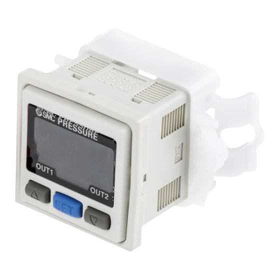
Summary of Product parts ○Names of individual parts Output (OUT1) lamp (Green): Lit when OUT1 is ON. Output (OUT2) lamp (Red): Lit when OUT2 is ON. LCD display: Displays the current status of pressure, setting mode, selected indication unit and error code. Four display modes can be selected: display always in red or green only, or changing from green to red linked to output. -
Page 11: Mounting And Installation
Mounting and Installation ■Installation <PSE3 > ○Mounting ●Mount the optional bracket and panel mount adapter to the product. ○Mounting by bracket ●Fix the bracket to the product with the set screws M3 x 5 L (2 pcs.) as attached. ●The tightening torque of the set screws must be 0.5 to 0.7 Nm. ○Mounting by panel mount adapter ●Fix the panel mount adapter to the product with the set screws M3 x 8 L (2 pcs.) as attached. - Page 12 <PSE3 T> ●Mounting Hang the Hook 1 at the bottom of the body on the DIN rail as shown in Fig. a, press it in arrowed direction to fix. ●Removing For removal, pull it with a flat driver in arrowed direction shown in Fig. b. -11- No.PS※※-OMG0002-G...
-
Page 13: Wiring
■Wiring ○Connection ●Connections should only be made with the power supply turned off. ●Use separate routes for the product wiring and any power or high voltage wiring. Otherwise, malfunction may result due to noise. ●Ensure that the FG terminal is connected to ground when using a commercially available switch-mode power supply. - Page 14 ●The core of the corresponding colour shown in the following table is put into the pin of the number stamped on the connector for sensor connection to the back. Colour of cable core Number stamped PSE31 (Current input) on connector PSE30 (Voltage input) Pressure sensor 2-wire type Pressure sensor 3-wire type...
-
Page 15: Internal Circuit And Wiring Example
○Connector Connecting/Disconnecting ●When connecting the connector, insert it straight onto the pin holding the lever and connector body between fingers and lock the connector by pushing the lever claw into the square groove in the housing until connector clicks. ●When disconnecting the connector, push down the lever by thumb to disengage the lever claw from the square groove. - Page 16 ○Output specification ●When the cable with SMC power and output cable (Model: ZS-28-A) is used, the colors of wire (Brown, Black, White, Gray, Blue) will apply as shown on circuit diagram. PSE3 0(T) PSE3 1(T) NPN open collector output: 2 outputs NPN open collector output: 2 outputs Max.
-
Page 17: Setting
Setting ○Setting procedures ○Initial setting Keep pressing the button longer than two seconds. Remove the finger off the button when [Sor] is displayed and initial setting can get started. 1. Display colour setting Select a colour for the LCD display. When changing the display colour, press the button to select a display colour. - Page 18 5. Output method setting Four output mode can be selected by an operating mode and by output style. One of these four output mode can be selected for each output. OUT1 and OUT2 can be set independently. Refer to "List of output mode". 1) The operating mode for OUT1 is set.
- Page 19 6. Response time setting A response time for switch output can be set as user desires. Set the optimum response time to prevent the chattering of a switch. The response time currently set will be displayed. Select a desired response time by pressing the button.
-
Page 20: Pressure Setting
Pressure Setting ○Manual setting Manually set a set value of the product. 1. Selection of OUT1 [P_1] setting mode Press the button during the Measurement mode to display set values. [P_1] and the current set value will displays in turn. (In case the Normally Closed mode is selected in initialization, [n_1] and the set value will displays in turn.) Press the... - Page 21 ○Auto-preset In case auto preset is selected in Initialize, this function stores in the memory a pressure setting value which is calculated from a measurement pressure as a reference value. The set value of product is automatically set to an optimum value by repeating absorption and non-absorption several times with a sample which is to be set up.
-
Page 22: Other Functions
Other Functions ○Auto shift function In case the source pressure fluctuates too much, the product may not be able to operate normally. Auto shift is provided to compensate for the fluctuation of the source pressure. While measured pressure becomes standard pressure value when auto shift input is received, this function correct set value of the switches. - Page 23 ○Peak and bottom hold display function Maximum and minimum values are always detected and updated during measurement. Displayed values can be held. In peak hold, press the button for longer than one second to make flicker and to hold the maximum pressure value.
-
Page 24: Maintenance
Maintenance How to reset the product for power cut or forcible de-energizing The setting of the product is remained as that before power cut or de-energizing. The output condition is also basically recovered to that before power cut or de-energizing, but may change depending on the operating environment. -
Page 25: Troubleshooting
Troubleshooting ○Troubleshooting Applicable pressure switch: PSE300 If a cause applicable to the failure cannot be identified and normal operation can be recovered by replacement with a new Pressure switch, this indicates that the Pressure switch itself was broken. The Pressure switch breakage can be caused by operating environment (network construction, etc.), and so consult with SMC separately to obtain countermeasures. - Page 26 Refer to reference The display fluctuates The display is abnormal No.8 Refer to reference The display disappears No.9 Refer to reference The display breaks off No.9 Refer to reference The display flashes No.10 Pressure indication Refer to reference difference when using No.11 two or more pressure switches...
- Page 27 ○Cross-reference for troubleshooting Reference Problem Possible cause Investigation method Countermeasure Output remains (1)Check the set pressure. (2)Check the settings of the Indication light operation mode, hysteresis and (1)Reset the pressure setting. Wrong pressure remains on. output style. (2)Reset the setting of setting (Hysteresis mode/window function.
- Page 28 Reference Problem Possible cause Investigation method Countermeasure Check if the analogue output line is Incorrect wiring Correct the wiring. connected with a load. (1) Check if the proper load is Non-compliance connected. with the load (2) Check if input impedance of Connect a proper load.
- Page 29 Reference Problem Possible cause Investigation method Countermeasure Incorrect power Check if the power supply voltage Supply power supply voltage supply is within the range of 12 to 24 VDC. of 12 to 24 VDC. Check the wiring to the power Indicated values supply.
- Page 30 Reference Problem Possible cause Investigation method Countermeasure "M" in the part number means Improper model that the unit cannot be selection changed. Check if there is a "-M" at the end of : The unit change function is not (Selection of the part number printed on the The unit cannot model "without...
- Page 31 ○Error indication function This function displays error location and nature when a problem or an error occurs. Error Name Error Display Error Type Troubleshooting OUT1 Over Turn the power off and remove the A load current of switch output is 80 mA current output factor for the over current.
-
Page 32: Specification
Specification ■Specifications Model No. PSE3 Applicable pressure For low For low For compound For vacuum For positive sensor pressure differential Rated pressure range -100 to 100 kPa 0 to -101 kPa 0 to 100 kPa 0 to 1 MPa 0 to 500 kPa 0 to 2 kPa 1 Set pressure range... - Page 33 Model No. PSE3 Enclosure IP40 Operation: 0 to 50 C, Storage: -10 to 60 C (No condensation or freezing) Ambient temp. range Ambient humidity range Operation, Storage: 35 to 85%RH (No condensation) Withstand voltage 1000 VAC, 1 minute Between lead block and case Insulation resistance 50 MΩ...
-
Page 34: Dimensions
■Dimensions ○Body dimensions ○Mounting using mounting option Mounting by bracket Mounting by panel mount -33- No.PS※※-OMG0002-G... - Page 35 ○Panel cutout dimension : Panel thickness: 0.5 to 6 mm -34- No.PS※※-OMG0002-G...
- Page 36 ○PSE3 -35- No.PS※※-OMG0002-G...
- Page 37 Revision history C: Revision and Format change. D: Contents revised in several places. E: Contents revised in several places. F: Contents revised in several places. G: Contents revised in several places. [July 2018] 4-14-1, Sotokanda, Chiyoda-ku, Tokyo 101-0021 JAPAN Tel: + 81 3 5207 8249 Fax: +81 3 5298 5362 http://www.smcworld.com Note: Specifications are subject to change without prior notice and any obligation on the part of the manufacturer.
Need help?
Do you have a question about the PSE303-LBC and is the answer not in the manual?
Questions and answers