Table of Contents
Advertisement
Quick Links
This document is a description of the
the capabilities that the RF430FRL152H device offers. To more easily experiment with all of the features
of the device and the firmware that is in the ROM, a PC application is available, and its use is also
described here, including software and driver installation.
The
family
of
RF430FRL154H.
...................................................................................................................
1
1.1
1.2
1.3
1.4
1.5
1.6
2
2.1
2.2
2.3
3
.....................................................................................................................
4
4.1
4.2
4.3
4.4
4.5
4.6
4.7
4.8
4.9
5
5.1
5.2
5.3
6
7
7.1
7.2
8
..................................................................................................................
9
1
2
3
4
SLAU607C - December 2014 - Revised July 2018
Submit Documentation Feedback
RF430FRL152HEVM User's Guide
RF430FRL152HEVM
RF430RL15xH
devices
.............................................................................................................
....................................................................................................
.........................................................................................
........................................................................................
.......................................................................................................
.......................................................................................................
.................................................................................................
..........................................................................................
............................................................................................................
...........................................................................................
.................................................................................................
..........................................................................................................
...................................................................................................
........................................................................................
.................................................................................................
............................................................................................
....................................................................................................
....................................................................................
................................................................................................
..........................................................................................................
............................................................................................
........................................................................................
........................................................................................................
.........................................................................................
..............................................................................................................
Copyright © 2014-2018, Texas Instruments Incorporated
SLAU607C - December 2014 - Revised July 2018
product that is designed to fully explore all of
includes
the
RF430FRL152H,
Contents
............................................................................
..........................................................................
..............................................................................
...........................................................................
.......................................................
List of Figures
User's Guide
RF430FRL153H,
..................................
..................
...................
RF430FRL152HEVM User's Guide
and
3
3
4
4
6
6
6
7
7
8
8
10
11
11
11
12
13
14
17
18
19
20
21
21
22
23
26
27
27
28
30
34
4
4
5
5
1
Advertisement
Table of Contents

Subscribe to Our Youtube Channel
Related Manuals for Texas Instruments RF430RL15 H Series


Summary of Contents for Texas Instruments RF430RL15 H Series
-
Page 1: Table Of Contents
List of Figures ......................RF430FRL152HEVM ....MSP-EXP430G2 LaunchPad Development Kit With TRF7970A BoosterPack Plug-in Module ..................MSP-EXP430G2 Jumper Settings ......................TRF7970AEVM SLAU607C – December 2014 – Revised July 2018 RF430FRL152HEVM User's Guide Submit Documentation Feedback Copyright © 2014–2018, Texas Instruments Incorporated... - Page 2 JTAG Section Schematic ....................Power Section Schematic Trademarks BoosterPack, MSP430, LaunchPad are trademarks of Texas Instruments. All other trademarks are the property of their respective owners. RF430FRL152HEVM User's Guide SLAU607C – December 2014 – Revised July 2018 Submit Documentation Feedback...
-
Page 3: Introduction
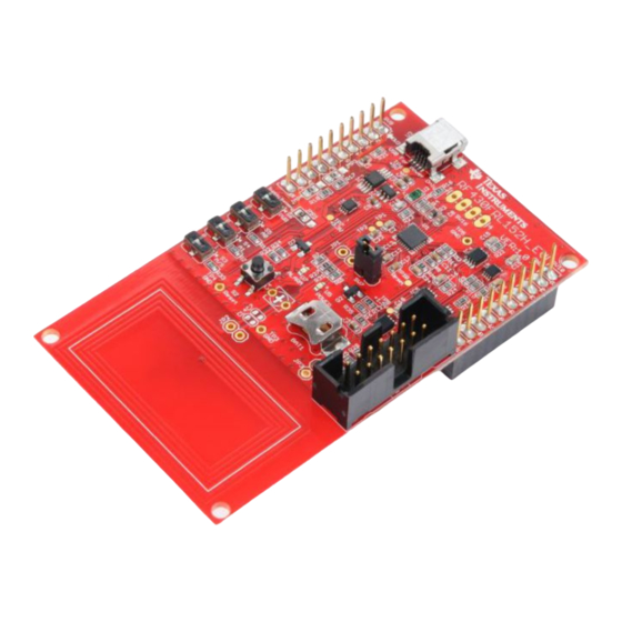
Connector to enable compatibility with TI LaunchPad™ development kits and BoosterPack plug-in modules • JTAG header for connection of MSP430-FET Emulation tool for programming SLAU607C – December 2014 – Revised July 2018 RF430FRL152HEVM User's Guide Submit Documentation Feedback Copyright © 2014–2018, Texas Instruments Incorporated... -
Page 4: What Is Included
To be used with the demo GUI, the MSP-EXP430G2 must be programmed with a special binary image (TRF7970A_BoosterPack_MSP430G2.out). This binary image can be found in the Debug folder of the zip file available at www.ti.com/lit/zip/sloc346. RF430FRL152HEVM User's Guide SLAU607C – December 2014 – Revised July 2018 Submit Documentation Feedback Copyright © 2014–2018, Texas Instruments Incorporated... -
Page 5: Msp-Exp430G2 Jumper Settings
TRF7970AEVM is programmed with the default EVM firmware, which can be downloaded from http://www.ti.com/lit/zip/sloc300. Figure 4. TRF7970AEVM SLAU607C – December 2014 – Revised July 2018 RF430FRL152HEVM User's Guide Submit Documentation Feedback Copyright © 2014–2018, Texas Instruments Incorporated... -
Page 6: Recommended Additional Equipment
2. Run the executable and follow the prompts to install the software. 3. To run the application click on the Start menu, All Programs, then the Texas Instruments folder, then the "RF430FRL152HEVM Application" and finally the "RF430FRL152H GUI Interface" program. -
Page 7: Hardware Description
RF430FRL152H. It is normal for the Alarm LED to stay lit during MSP-FET tool programming. SLAU607C – December 2014 – Revised July 2018 RF430FRL152HEVM User's Guide Submit Documentation Feedback Copyright © 2014–2018, Texas Instruments Incorporated... -
Page 8: Hardware Overview
This is normal behavior. The MSP-FET emulation tool can be used to program or debug the EVM at this point. RF430FRL152HEVM User's Guide SLAU607C – December 2014 – Revised July 2018 Submit Documentation Feedback Copyright © 2014–2018, Texas Instruments Incorporated... - Page 9 Note: If a battery is installed and another configuration (for example, debugging or using a BoosterPack plug-in module) is required, set switch S6 to "Supply" to disconnect the battery and not drain it. SLAU607C – December 2014 – Revised July 2018 RF430FRL152HEVM User's Guide Submit Documentation Feedback Copyright © 2014–2018, Texas Instruments Incorporated...
-
Page 10: Gui Introduction
After a sampling process has completed, this tab allows the user to view the logged data. System Settings to the system control register can be made here. RF430FRL152HEVM User's Guide SLAU607C – December 2014 – Revised July 2018 Submit Documentation Feedback Copyright © 2014–2018, Texas Instruments Incorporated... -
Page 11: Overview
4. After sampling is complete, the requested measurements are stored into the log memory, typically FRAM (after the virtual registers). SLAU607C – December 2014 – Revised July 2018 RF430FRL152HEVM User's Guide Submit Documentation Feedback Copyright © 2014–2018, Texas Instruments Incorporated... -
Page 12: Setup Tab
3. If the RF430FRL152HEVM is selected, an option to select whether or not a Sensor Hub BoosterPack plug-in module is being used is presented. Make the selection (see Figure Figure 9. Setup Tab RF430FRL152HEVM User's Guide SLAU607C – December 2014 – Revised July 2018 Submit Documentation Feedback Copyright © 2014–2018, Texas Instruments Incorporated... -
Page 13: Demo Mode Tab
Setup tab, then pressing the "Start Demo" button, measurement will be started and temperature data and other sensor data like light intensity will be shown (see Figure 10). Figure 10. Demo Tab SLAU607C – December 2014 – Revised July 2018 RF430FRL152HEVM User's Guide Submit Documentation Feedback Copyright © 2014–2018, Texas Instruments Incorporated... -
Page 14: General Device Configuration Tab
8. Sensor Control Register Allows the selection of any sensor to be sampled. Selection of one or multiple sensors is possible. RF430FRL152HEVM User's Guide SLAU607C – December 2014 – Revised July 2018 Submit Documentation Feedback Copyright © 2014–2018, Texas Instruments Incorporated... - Page 15 23. Bus Test Mode Enable Allows access to protected memory using an I C or SPI host. SLAU607C – December 2014 – Revised July 2018 RF430FRL152HEVM User's Guide Submit Documentation Feedback Copyright © 2014–2018, Texas Instruments Incorporated...
- Page 16 Likewise, the settings on these tabs are not updated until a "Read only this tab" or "Read All Tabs" button is clicked. RF430FRL152HEVM User's Guide SLAU607C – December 2014 – Revised July 2018 Submit Documentation Feedback Copyright © 2014–2018, Texas Instruments Incorporated...
-
Page 17: Sensor Configuration Tab
This is a counter that indicates how many ISO/IEC blocks have been received. Can be reset. 9. Sensor Skip Settings Allows control of the duty cycle for a sensor. SLAU607C – December 2014 – Revised July 2018 RF430FRL152HEVM User's Guide Submit Documentation Feedback Copyright © 2014–2018, Texas Instruments Incorporated... -
Page 18: Alarm Control Tab
8. Reset Status Flags on This Tab On Next Write Resets all of the flags on this tab the next time the "Write" button is clicked. RF430FRL152HEVM User's Guide SLAU607C – December 2014 – Revised July 2018 Submit Documentation Feedback Copyright © 2014–2018, Texas Instruments Incorporated... -
Page 19: Sensor Threshold Configuration Tab
If the sensor sample result is lower or meets the low threshold set here, an alarm is generated. Operation depends on settings in the "Alarm Control" tab. SLAU607C – December 2014 – Revised July 2018 RF430FRL152HEVM User's Guide Submit Documentation Feedback Copyright © 2014–2018, Texas Instruments Incorporated... -
Page 20: View Sensor Data Tab
GUI before clicking the button, because the settings are used to determine what type of sampling process occurred. Figure 15. View Sensor Data Tab RF430FRL152HEVM User's Guide SLAU607C – December 2014 – Revised July 2018 Submit Documentation Feedback Copyright © 2014–2018, Texas Instruments Incorporated... -
Page 21: Setup Of Demo System
7. Click the "Connect to TRF7970AEVM" button on the bottom of the window. 8. A few seconds after you click the "Connect" button, the label next to the button should show SLAU607C – December 2014 – Revised July 2018 RF430FRL152HEVM User's Guide Submit Documentation Feedback Copyright © 2014–2018, Texas Instruments Incorporated... -
Page 22: Set Up The Rf430Frl152Hevm Demo Using The Pc
17. It is recommended to have an insulator between the two antennas or to hold them at a distance from each other to prevent any short circuits. RF430FRL152HEVM User's Guide SLAU607C – December 2014 – Revised July 2018 Submit Documentation Feedback Copyright © 2014–2018, Texas Instruments Incorporated... -
Page 23: Using The Pc Application For Advanced Custom Control Of The Rf430Frl152Hevm
The CIC filter allows for shorter conversion times (using 256 oversampling). SLAU607C – December 2014 – Revised July 2018 RF430FRL152HEVM User's Guide Submit Documentation Feedback Copyright © 2014–2018, Texas Instruments Incorporated... -
Page 24: Custom Sensor Configuration Tab
11. Check "Start Sampling Process". Figure 19 shows the "Gen. Device Config" tab with these settings. RF430FRL152HEVM User's Guide SLAU607C – December 2014 – Revised July 2018 Submit Documentation Feedback Copyright © 2014–2018, Texas Instruments Incorporated... -
Page 25: Custom General Device Configuration
However, the GUI shows which sensor is sampled and the expected order. Figure 20. Custom View Data SLAU607C – December 2014 – Revised July 2018 RF430FRL152HEVM User's Guide Submit Documentation Feedback Copyright © 2014–2018, Texas Instruments Incorporated... -
Page 26: Changing Firmware System Settings
"Write" button to send them over RF. To automatically set the setting for the PC application, click "Write Settings For This GUI". RF430FRL152HEVM User's Guide SLAU607C – December 2014 – Revised July 2018 Submit Documentation Feedback Copyright © 2014–2018, Texas Instruments Incorporated... -
Page 27: Over-The-Air Programming
8. After programming completes, power down the RF430FRL15xH by removing it from the field or disconnecting the power supply. When power is applied again, the RF430FRL15xH resets and the new program takes effect. SLAU607C – December 2014 – Revised July 2018 RF430FRL152HEVM User's Guide Submit Documentation Feedback Copyright © 2014–2018, Texas Instruments Incorporated... -
Page 28: Generating A Txt File
-romwidth 16 4. Compile the project. The .txt binary output is saved to the “Debug” folder. Figure 24. CCS TXT Generation RF430FRL152HEVM User's Guide SLAU607C – December 2014 – Revised July 2018 Submit Documentation Feedback Copyright © 2014–2018, Texas Instruments Incorporated... -
Page 29: Iar Txt Generation
3. Select the “msp430-txt” setting in the “Output format”. Leave “Format variant” set to “None”. 4. Compile the project. The .txt binary output is saved to the “Debug” folder. Figure 25. IAR TXT Generation SLAU607C – December 2014 – Revised July 2018 RF430FRL152HEVM User's Guide Submit Documentation Feedback Copyright © 2014–2018, Texas Instruments Incorporated... -
Page 30: Rf430Frl152Hevm Schematics
RF430FRL152HEVM Schematics www.ti.com RF430FRL152HEVM Schematics A single full-sheet schematic is available here. Figure 26. MCU Section Schematic RF430FRL152HEVM User's Guide SLAU607C – December 2014 – Revised July 2018 Submit Documentation Feedback Copyright © 2014–2018, Texas Instruments Incorporated... -
Page 31: C Or Spi Translators Section Schematic
RF430FRL152HEVM Schematics www.ti.com Figure 27. I C or SPI Translators Section Schematic SLAU607C – December 2014 – Revised July 2018 RF430FRL152HEVM User's Guide Submit Documentation Feedback Copyright © 2014–2018, Texas Instruments Incorporated... -
Page 32: Jtag Section Schematic
RF430FRL152HEVM Schematics www.ti.com Figure 28. JTAG Section Schematic RF430FRL152HEVM User's Guide SLAU607C – December 2014 – Revised July 2018 Submit Documentation Feedback Copyright © 2014–2018, Texas Instruments Incorporated... -
Page 33: Power Section Schematic
RF430FRL152HEVM Schematics www.ti.com Figure 29. Power Section Schematic SLAU607C – December 2014 – Revised July 2018 RF430FRL152HEVM User's Guide Submit Documentation Feedback Copyright © 2014–2018, Texas Instruments Incorporated... -
Page 34: References
The primary sources of RF430FRL15xH information are: RF430FRL152H Evaluation Module Sensor Hub BoosterPack plug-in module TRF7970A Evaluation Module Near Field Communications Overview Low-Power Microcontrollers Overview RF430FRL152HEVM User's Guide SLAU607C – December 2014 – Revised July 2018 Submit Documentation Feedback Copyright © 2014–2018, Texas Instruments Incorporated... - Page 35 Removed paragraph with obsolete information about location of MSP430G2_TRF7970ABP_Binary.out in Section 1.3.1, ........ MSP-EXP430G2 LaunchPad Development Kit With TRF7970A BoosterPack Plug-in Module ....................• Updated Section 1.3.2, TRF7970AEVM SLAU607C – December 2014 – Revised July 2018 Revision History Submit Documentation Feedback Copyright © 2014–2018, Texas Instruments Incorporated...
- Page 36 STANDARD TERMS FOR EVALUATION MODULES Delivery: TI delivers TI evaluation boards, kits, or modules, including any accompanying demonstration software, components, and/or documentation which may be provided together or separately (collectively, an “EVM” or “EVMs”) to the User (“User”) in accordance with the terms set forth herein.
- Page 37 FCC Interference Statement for Class B EVM devices NOTE: This equipment has been tested and found to comply with the limits for a Class B digital device, pursuant to part 15 of the FCC Rules. These limits are designed to provide reasonable protection against harmful interference in a residential installation.
- Page 38 【無線電波を送信する製品の開発キットをお使いになる際の注意事項】 開発キットの中には技術基準適合証明を受けて いないものがあります。 技術適合証明を受けていないもののご使用に際しては、電波法遵守のため、以下のいずれかの 措置を取っていただく必要がありますのでご注意ください。 1. 電波法施行規則第6条第1項第1号に基づく平成18年3月28日総務省告示第173号で定められた電波暗室等の試験設備でご使用 いただく。 2. 実験局の免許を取得後ご使用いただく。 3. 技術基準適合証明を取得後ご使用いただく。 なお、本製品は、上記の「ご使用にあたっての注意」を譲渡先、移転先に通知しない限り、譲渡、移転できないものとします。 上記を遵守頂けない場合は、電波法の罰則が適用される可能性があることをご留意ください。 日本テキサス・イ ンスツルメンツ株式会社 東京都新宿区西新宿6丁目24番1号 西新宿三井ビル 3.3.3 Notice for EVMs for Power Line Communication: Please see http://www.tij.co.jp/lsds/ti_ja/general/eStore/notice_02.page 電力線搬送波通信についての開発キットをお使いになる際の注意事項については、次のところをご覧ください。http:/ /www.tij.co.jp/lsds/ti_ja/general/eStore/notice_02.page 3.4 European Union 3.4.1 For EVMs subject to EU Directive 2014/30/EU (Electromagnetic Compatibility Directive): This is a class A product intended for use in environments other than domestic environments that are connected to a low-voltage power-supply network that supplies buildings used for domestic purposes.
- Page 39 Notwithstanding the foregoing, any judgment may be enforced in any United States or foreign court, and TI may seek injunctive relief in any United States or foreign court. Mailing Address: Texas Instruments, Post Office Box 655303, Dallas, Texas 75265 Copyright © 2018, Texas Instruments Incorporated...
- Page 40 IMPORTANT NOTICE FOR TI DESIGN INFORMATION AND RESOURCES Texas Instruments Incorporated (‘TI”) technical, application or other design advice, services or information, including, but not limited to, reference designs and materials relating to evaluation modules, (collectively, “TI Resources”) are intended to assist designers who are developing applications that incorporate TI products;...
- Page 41 Mouser Electronics Authorized Distributor Click to View Pricing, Inventory, Delivery & Lifecycle Information: Texas Instruments RF430FRL152HEVM...
Need help?
Do you have a question about the RF430RL15 H Series and is the answer not in the manual?
Questions and answers