Table of Contents
Advertisement
Quick Links
www.ti.com
EVM User's Guide: RS485FLDPLXDRCEVM
RS485FLDPLXDRCEVM Evaluation Module
Description
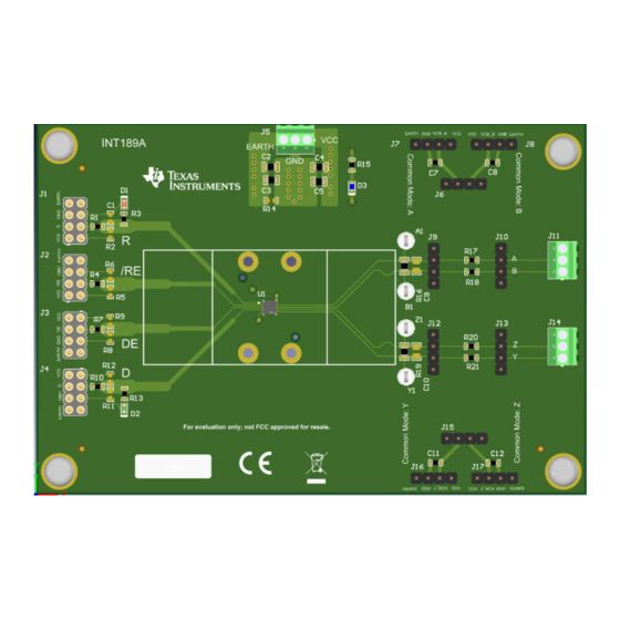
The RS485FLDPLXDRCEVM is an EVM from TI
that allows quick prototyping of our Full Duplex
RS-485 Transceivers in a DRC package. The board
allows for testing of single and differential ended
communication with potential modifications such as
changing the termination resistance or adding a
common mode bias to the bus to simulate ground
potential differences that can be seen in systems
with long cables that share a ground line with
high current capacity. The board comes preinstalled
with a THVD2412DRCR which allows full duplex
communication at up to 250kbps powered by a 3 V
to 5.5V power connection on VCC. The board also
supports testing of systems with separate EARTH
planes separate from the device ground reference
plane.
Features
•
Footprint for 10-Pin VSON (DRC) Full Duplex
RS-485 Transceivers Indicated as U1
•
THVD2412DRC Installed as U1 by Default
RS485FLDPLXDRCEVM - Front View
SLLU376 – DECEMBER 2023
Submit Document Feedback
•
Power Supply Terminals allow for Power, Board-
Ground, and Earth Connections.
•
Bulk Power Supply Coupling Capacitors installed
(2, 47uF and 2, 10uF caps) with two between VCC
and GND with the other two between GND and
EARTH.
•
Ground Current Limiting Resistor Pad (R14)
Available Between Board Ground and Earth on J5
•
Common Mode Voltage Connections (J6, J7, J8,
J15, J16, and J17) Available to Add a Common
Mode Voltage to the RS-485 Differential Bus (Pins
A and B or Pins Y and Z)
Applications
•
Motor drives
•
Factory automation and control
•
HVAC systems
•
Building automation
•
Grid infrastructure
•
Electricity meters
•
Process analytics
•
Video surveillance
Copyright © 2023 Texas Instruments Incorporated
RS485FLDPLXDRCEVM - Back View
RS485FLDPLXDRCEVM Evaluation Module
Description
1
Advertisement
Table of Contents

Related Manuals for Texas Instruments RS485FLDPLXDRCEVM


Summary of Contents for Texas Instruments RS485FLDPLXDRCEVM
- Page 1 • Power Supply Terminals allow for Power, Board- Description Ground, and Earth Connections. The RS485FLDPLXDRCEVM is an EVM from TI • Bulk Power Supply Coupling Capacitors installed that allows quick prototyping of our Full Duplex (2, 47uF and 2, 10uF caps) with two between VCC RS-485 Transceivers in a DRC package.
-
Page 2: Kit Contents
This user’s guide describes the RS485FLDPLXDRCEVM and the intended use. This document is the EVM user’s guide for the RS485FLDPLXDRCEVM, which provides a quick way to evaluate TI’s Full Duplex RS-485 Transceivers in 10-Pin VSON (DRC) Packages such as the THVD2412DRC. For more detailed description of operation, check the specific DUT data sheet (SLLSFR1). - Page 3 2 Hardware 2.1 Board Components and Pad Overview The RS485FLDPLXDRCEVM Comes Ready to Operate Directly Out of Box with a THVD2412DRCR installed at U1. All the Signal and Power Jumpers/Inputs (J1 – J15) come pre-installed on board. Table 2-1. Jumpers...
- Page 4 Comes pre-installed with (10 Pin VSSON) Package THVD2412DRC The default setup is optimized to work with the THVD2412DRCR operating without a common mode voltage. RS485FLDPLXDRCEVM Evaluation Module SLLU376 – DECEMBER 2023 Submit Document Feedback Copyright © 2023 Texas Instruments Incorporated...
-
Page 5: Power Requirements
2.2 Power Requirements The RS485FLDPLXDRCEVM is ready to operate immediately outside of the box. To power the board, find J5 at the top center of the board. For systems with both GND and EARTH signals, attach the EARTH lead to the left most pin of J5 next to the text that displays EARTH and attach the GND lead to the center input of J5 above the text that displays GND. - Page 6 Common Mode Resistor Pad, 0603, to “Y” J12, J13, J14 | Y and Z Termination Capacitor Pad, 0805 J12, J13, J14 | Y and Z Termination Resistor Pad, 0805 RS485FLDPLXDRCEVM Evaluation Module SLLU376 – DECEMBER 2023 Submit Document Feedback Copyright © 2023 Texas Instruments Incorporated...
- Page 7 Hardware Design Files 3 Hardware Design Files 3.1 Schematics Figure 3-1. Generic Schematic - All Components Shown SLLU376 – DECEMBER 2023 RS485FLDPLXDRCEVM Evaluation Module Submit Document Feedback Copyright © 2023 Texas Instruments Incorporated...
- Page 8 Hardware Design Files www.ti.com Figure 3-2. Schematic - Installed Components Only RS485FLDPLXDRCEVM Evaluation Module SLLU376 – DECEMBER 2023 Submit Document Feedback Copyright © 2023 Texas Instruments Incorporated...
-
Page 9: Pcb Layouts
Hardware Design Files 3.2 PCB Layouts Figure 3-3. Top Layer Figure 3-4. Bottom Layer SLLU376 – DECEMBER 2023 RS485FLDPLXDRCEVM Evaluation Module Submit Document Feedback Copyright © 2023 Texas Instruments Incorporated... -
Page 10: Bill Of Materials (Bom)
All trademarks are the property of their respective owners. 5 References THVD24x2 ±70-V Fault-Protected 3-V to 5.5-V Full Duplex RS-485 Transceivers With IEC ESD data sheet (SLLSFR1). RS485FLDPLXDRCEVM Evaluation Module SLLU376 – DECEMBER 2023 Submit Document Feedback Copyright © 2023 Texas Instruments Incorporated... - Page 11 STANDARD TERMS FOR EVALUATION MODULES Delivery: TI delivers TI evaluation boards, kits, or modules, including any accompanying demonstration software, components, and/or documentation which may be provided together or separately (collectively, an “EVM” or “EVMs”) to the User (“User”) in accordance with the terms set forth herein.
- Page 12 www.ti.com Regulatory Notices: 3.1 United States 3.1.1 Notice applicable to EVMs not FCC-Approved: FCC NOTICE: This kit is designed to allow product developers to evaluate electronic components, circuitry, or software associated with the kit to determine whether to incorporate such items in a finished product and software developers to write software applications for use with the end product.
- Page 13 www.ti.com Concernant les EVMs avec antennes détachables Conformément à la réglementation d'Industrie Canada, le présent émetteur radio peut fonctionner avec une antenne d'un type et d'un gain maximal (ou inférieur) approuvé pour l'émetteur par Industrie Canada. Dans le but de réduire les risques de brouillage radioélectrique à...
- Page 14 www.ti.com EVM Use Restrictions and Warnings: 4.1 EVMS ARE NOT FOR USE IN FUNCTIONAL SAFETY AND/OR SAFETY CRITICAL EVALUATIONS, INCLUDING BUT NOT LIMITED TO EVALUATIONS OF LIFE SUPPORT APPLICATIONS. 4.2 User must read and apply the user guide and other available documentation provided by TI regarding the EVM prior to handling or using the EVM, including without limitation any warning or restriction notices.
- Page 15 Notwithstanding the foregoing, any judgment may be enforced in any United States or foreign court, and TI may seek injunctive relief in any United States or foreign court. Mailing Address: Texas Instruments, Post Office Box 655303, Dallas, Texas 75265 Copyright © 2023, Texas Instruments Incorporated...
-
Page 16: Important Notice
TI products. TI’s provision of these resources does not expand or otherwise alter TI’s applicable warranties or warranty disclaimers for TI products. TI objects to and rejects any additional or different terms you may have proposed. IMPORTANT NOTICE Mailing Address: Texas Instruments, Post Office Box 655303, Dallas, Texas 75265 Copyright © 2023, Texas Instruments Incorporated... -
Page 17: Texas Instruments
Mouser Electronics Authorized Distributor Click to View Pricing, Inventory, Delivery & Lifecycle Information: Texas Instruments RS485FLDPLXDRCEVM...
Need help?
Do you have a question about the RS485FLDPLXDRCEVM and is the answer not in the manual?
Questions and answers