Advertisement
Quick Links
This manual describes the RS-485 Half-Duplex Evaluation Module (EVM). This EVM helps designers
evaluate the device performance, supporting the fast development and analysis of data transmission
systems using any of the TI RS-485 half-duplex devices.
.....................................................................................................................
1
Overview
2
EVM Setup and Precautions
3
Powering Up the EVM and Taking Measurements
3.1
Measurement Examples
1
RS-485 Half-Duplex EVM Schematic
2
Bridging DUT_GND with EARTH_GND
3
Example for Stimulus and Probe Points with JMP4 and JMP14
4
Transceiver Configuration for Normal Operation
5
RS-485 Half-Duplex EVM Setup for Normal Transceiver Operation
6
Configuration for Maximum Loading
7
RS-485 Half-Duplex EVM Setup for Maximum Loading
8
RS-485 Half-Duplex EVM Configurations: Left as Receiver EVM, Right as Transmitter EVM
9
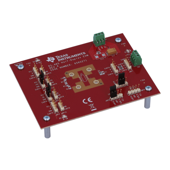
Top View of RS-485 Half-Duplex EVM
10
Bottom View of RS-485 Half-Duplex EVM
SLLU173A – October 2012 – Revised November 2012
Submit Documentation Feedback
RS-485 Half-Duplex Evaluation Module
Contents
..............................................................................................
.....................................................................
..........................................................................................
List of Figures
....................................................................................
..................................................................................
.......................................................................
......................................................................................
...............................................................
...................................................................................
...............................................................................
Copyright © 2012, Texas Instruments Incorporated
SLLU173A – October 2012 – Revised November 2012
.....................................................
.................................................
RS-485 Half-Duplex Evaluation Module
User's Guide
2
2
4
4
3
3
4
5
5
6
6
...................
7
7
8
1
Advertisement

Subscribe to Our Youtube Channel
Related Manuals for Texas Instruments RS485-HF-DPLX-EVM


Summary of Contents for Texas Instruments RS485-HF-DPLX-EVM
- Page 1 RS-485 Half-Duplex EVM Configurations: Left as Receiver EVM, Right as Transmitter EVM ................... Top View of RS-485 Half-Duplex EVM ................Bottom View of RS-485 Half-Duplex EVM SLLU173A – October 2012 – Revised November 2012 RS-485 Half-Duplex Evaluation Module Submit Documentation Feedback Copyright © 2012, Texas Instruments Incorporated...
- Page 2 Pin 3 (VCC) is connected to the positive output of a regulated power supply unit (PSU) as it represents the positive supply voltage of the device-under-test and also connects to various jumpers on the board. RS-485 Half-Duplex Evaluation Module SLLU173A – October 2012 – Revised November 2012 Submit Documentation Feedback Copyright © 2012, Texas Instruments Incorporated...
- Page 3 50-Ω resistors divide this voltage down to the correct signal level. SLLU173A – October 2012 – Revised November 2012 RS-485 Half-Duplex Evaluation Module Submit Documentation Feedback Copyright © 2012, Texas Instruments Incorporated...
- Page 4 A and B. Via the active receiver, it is possible to sense the data traffic in transmit direction. RS-485 Half-Duplex Evaluation Module SLLU173A – October 2012 – Revised November 2012 Submit Documentation Feedback Copyright © 2012, Texas Instruments Incorporated...
- Page 5 55 mA. The purpose of this test is to show the robustness of V over the entire common- mode voltage range at maximum load. SLLU173A – October 2012 – Revised November 2012 RS-485 Half-Duplex Evaluation Module Submit Documentation Feedback Copyright © 2012, Texas Instruments Incorporated...
- Page 6 , connect the ground terminal of PSU2 with pin 1 of TB1 (EARTH), and the V -output of PSU2 with the ground terminal of PSU1. RS-485 Half-Duplex Evaluation Module SLLU173A – October 2012 – Revised November 2012 Submit Documentation Feedback Copyright © 2012, Texas Instruments Incorporated...
- Page 7 Figure 8. RS-485 Half-Duplex EVM Configurations: Left as Receiver EVM, Right as Transmitter EVM Figure 9. Top View of RS-485 Half-Duplex EVM SLLU173A – October 2012 – Revised November 2012 RS-485 Half-Duplex Evaluation Module Submit Documentation Feedback Copyright © 2012, Texas Instruments Incorporated...
- Page 8 Figure 10. Bottom View of RS-485 Half-Duplex EVM For detailed information on the device parameters see the data sheet of the selected device at www.ti.com RS-485 Half-Duplex Evaluation Module SLLU173A – October 2012 – Revised November 2012 Submit Documentation Feedback Copyright © 2012, Texas Instruments Incorporated...
-
Page 9: Regulatory Compliance Information
Any exceptions to this are strictly prohibited and unauthorized by Texas Instruments unless user has obtained appropriate experimental/development licenses from local regulatory authorities, which is responsibility of user including its acceptable authorization. - Page 10 FCC Interference Statement for Class B EVM devices This equipment has been tested and found to comply with the limits for a Class B digital device, pursuant to part 15 of the FCC Rules. These limits are designed to provide reasonable protection against harmful interference in a residential installation. This equipment generates, uses and can radiate radio frequency energy and, if not installed and used in accordance with the instructions, may cause harmful interference to radio communications.
- Page 11 Also, please do not transfer this product, unless you give the same notice above to the transferee. Please note that if you could not follow the instructions above, you will be subject to penalties of Radio Law of Japan. Texas Instruments Japan Limited (address) 24-1, Nishi-Shinjuku 6 chome, Shinjuku-ku, Tokyo, Japan http://www.tij.co.jp...
- Page 12 FDA Class III or similar classification, then you must specifically notify TI of such intent and enter into a separate Assurance and Indemnity Agreement. Mailing Address: Texas Instruments, Post Office Box 655303, Dallas, Texas 75265 Copyright © 2012, Texas Instruments Incorporated...
-
Page 13: Important Notice
IMPORTANT NOTICE Texas Instruments Incorporated and its subsidiaries (TI) reserve the right to make corrections, enhancements, improvements and other changes to its semiconductor products and services per JESD46, latest issue, and to discontinue any product or service per JESD48, latest issue. - Page 14 Mouser Electronics Authorized Distributor Click to View Pricing, Inventory, Delivery & Lifecycle Information: Texas Instruments RS485-HF-DPLX-EVM...
Need help?
Do you have a question about the RS485-HF-DPLX-EVM and is the answer not in the manual?
Questions and answers